A swing guide rod driven stepless adjustment wave maker

A technology of stepless adjustment and swing guide rod, which is applied in the direction of fluid dynamics test, machine/structural component test, measuring device, etc. It can solve the problems of inconvenient switching and single switching position, and achieve stable waveform, convenient adjustment and good performance. The effect of force transmission characteristics

Inactive Publication Date: 2017-12-01
NINGBO INST OF TECH ZHEJIANG UNIV ZHEJIANG
View PDF8 Cites 0 Cited by
  • Summary
  • Abstract
  • Description
  • Claims
  • Application Information

AI Technical Summary

Problems solved by technology

Although such an actual wave maker can realize flat push, swing and push-swing composite motion, it is realized by switching the switch lever at A, B, and C points back and forth, and there are problems such as inconvenient switching and single switching position.

Method used


Image

  • A swing guide rod driven stepless adjustment wave maker
  • A swing guide rod driven stepless adjustment wave maker
  • A swing guide rod driven stepless adjustment wave maker

Examples


Embodiment 1

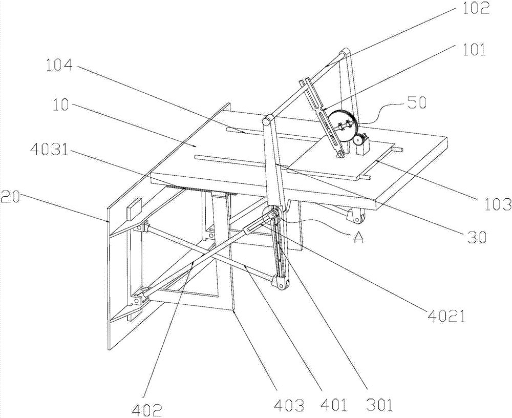
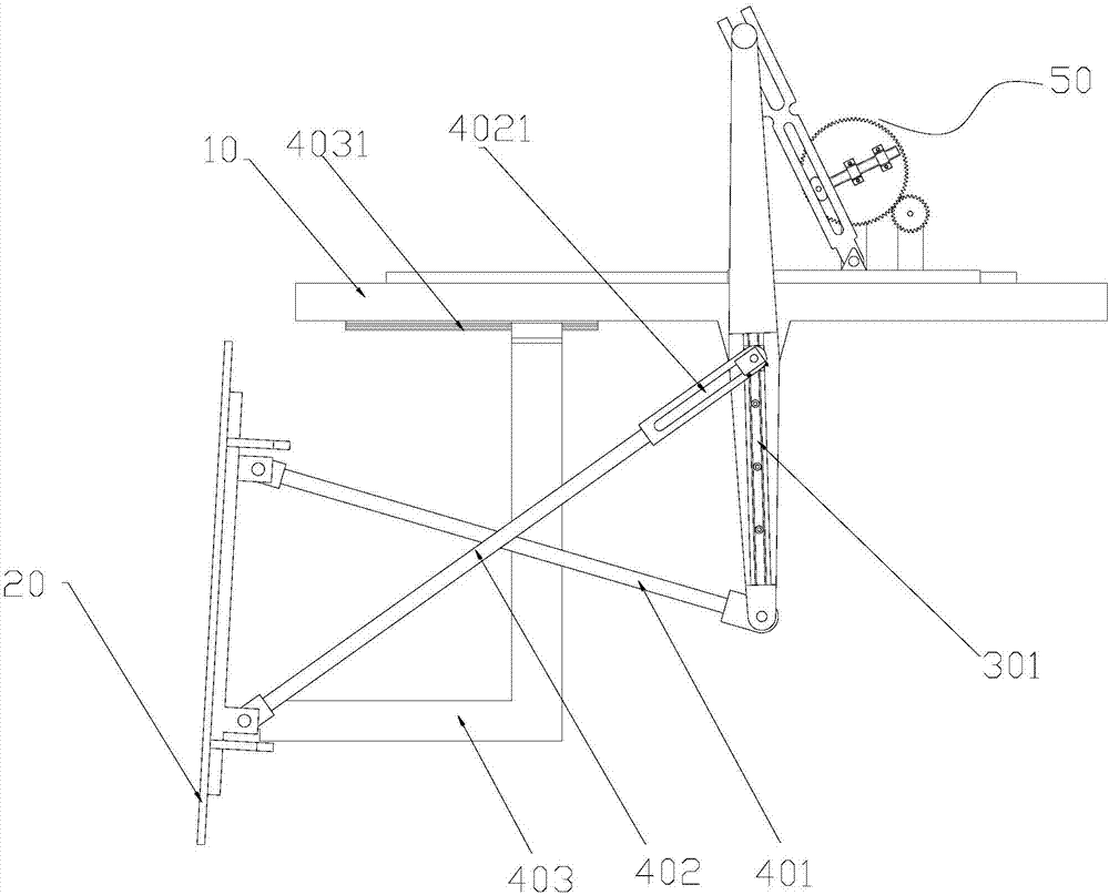
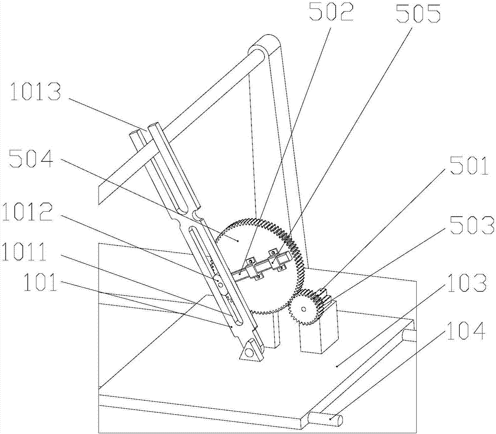
[0037] Such as Figure 1-3As shown, it is a structural schematic diagram of a swing guide rod driven stepless adjustment wave maker according to an embodiment of the present invention, a structural schematic diagram of a push rod mechanism and a structural schematic diagram of its driving mechanism, including a machine base 10, a rocker 101, a horizontal The rod 102, the push wave plate 20 arranged at the front end of the machine base 10, the driving device arranged above the machine base 10 for driving the movement of the push wave plate 20, and the force rods 30 symmetrically arranged on both sides of the machine base 10 and hinged with the machine base And the push rod mechanism that is symmetrically arranged on both sides of the machine base 10 and pushes the push wave plate 20 to move under the action of the drive device 50, wherein the drive device 50 further includes a motor 501, an adjustable crank 502, a pinion gear 503 that meshes with each other, and The large gear ...

Embodiment 2

[0048] Such as Figure 4 As shown in FIG. 1 , it is a structural schematic diagram of a lock-lock slider of a swing guide rod-driven steplessly adjustable wave maker according to another embodiment of the present invention. On the basis of Embodiment 1, in a specific application embodiment, an adjustment slot 4021 for adjusting the length of the auxiliary push rod 402 is provided at one end of the auxiliary push rod 402 connected to the first slide rail 301 .

[0049] In a specific application embodiment, the other end of the auxiliary push rod 402 is fixed on the first slide rail 301 through a locking slider, and the locking slider includes a first locking slider 404 and a second locking slider 405. The locking slider 404 is arranged on the first sliding rail 301 in a manner that can move freely on the first sliding rail 301, and the second locking slider 405 is arranged in the adjusting groove 4021 at the other end of the auxiliary push rod 402. The locking slider 404 and t...


PUM


Abstract

The invention discloses a swinging guide rod driving type stepless adjusting wave maker, comprising an engine base, a rocking bar, a cross bar, and a wave pushing plate arranged in the front end of the engine base, a drive device used for driving the wave pushing plate to move, force-bearing rods which are symmetrically arranged on two sides of the engine base and hinged with the engine base and pushing rod mechanisms which are symmetrically arranged on two sides of the engine base and push the wave-pushing plates to move under the action of the driving device. The driving device comprises a motor, an adjustable crank, a pinion and a bull gear which are intermeshed; the output end of the motor is connected to the pinion; the adjustable crank is fixed on the end surface of the bull gear through a fixing member; one end of the rocking bar is in rotation connection with the engine base, and the other end is connected to the cross bar; the two ends of the cross bar are connected to the force-bearing rod; a first sliding rail is arranged on the force-bearing rod; and the rod-pushing mechanism further comprises a main pushing rod, an auxiliary pushing rod and a moving pushing rod. The swinging guide rod driving type stepless adjusting wave maker can perform swinging movement as well as the pushing-swinging composite movement, and can realize the stepless adjustment from the swinging movement to the pushing-swinging composite movement. The switching is easy.

Description

technical field [0001] The invention belongs to the field of simulated wave-making machinery, and in particular relates to a wave-making machine with a swing guide rod-driven stepless adjustment. Background technique [0002] The wave maker is an instrument that can artificially create various waves in the experimental pool. There are many types of waves, generally including: regular waves, irregular waves, two-dimensional waves, three-dimensional waves and waves with special requirements. . It is a special equipment for simulation tests of ships, port engineering, wave power generation devices, etc. It is an indispensable device for indoor simulation of marine environments. [0003] The wave maker creates waves that meet specific needs through the reciprocating motion of the wave pushing plate placed at the front end of the equipment and placed in the water. Due to the complexity and diversity of experimental research, researchers have higher and higher requirements for w...

Claims


Application Information

Patent Timeline
Patent Type & Authority Patents(China)
IPC IPC(8): G01M10/00
CPCG01M10/00
Inventor 刘毅王登郑三和王贤成黄方平陈俊华
Owner NINGBO INST OF TECH ZHEJIANG UNIV ZHEJIANG
Why Eureka
Try Eureka