Common-path forward-reverse simultaneous measuring device for fiber optic gyroscope ring

A fiber optic gyroscope and measuring device technology, which is applied in measuring devices, gyroscopes/steering sensing equipment, Sagnac effect gyroscopes, etc., can solve the problem that the controllable reversing mechanism does not achieve simultaneity and cannot strictly control the consistency of the system , There is no way to achieve distributed measurement and other problems, to reduce measurement inconsistency, eliminate the impact of environmental factors, and reduce test time

Active Publication Date: 2017-10-24
HARBIN ENG UNIV
View PDF16 Cites 9 Cited by
  • Summary
  • Abstract
  • Description
  • Claims
  • Application Information

AI Technical Summary

Benefits of technology

This technology helps ensure that both directions of light traveling through an opto-electronic sensor have equal sensitivity when measuring its rotation rate or orientation angle with respect to another axis. It also allows for precise measurements without any external influences like temperatures or other sources affects the performance of this type of instrumentation.

Problems solved by technology

This patented describes various techniques related to measuring the alignment properties of fibers called saturated double waveguides (SSW), which plays a crucial role during the fabrication of optexybrid type fused silicon photon detectors (FPIC)-based Fibrocoupled Interferometric Quantum Domain Reflectometry Technique (QNDRTM TECHNICAL COMS Labs Technologies GmbH.). These technological improvements aim to provide accurate and uniform detection of both positive and negative errors in the Fiber Optic Gyro Ring (FOGYSCRZER®) due to factors like unmatchability of reflection mirror elements and imperfections such as misalignments among components.

Method used


Image

  • Common-path forward-reverse simultaneous measuring device for fiber optic gyroscope ring
  • Common-path forward-reverse simultaneous measuring device for fiber optic gyroscope ring
  • Common-path forward-reverse simultaneous measuring device for fiber optic gyroscope ring

Examples


Embodiment 1

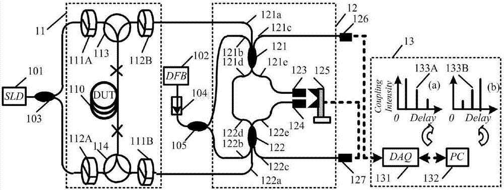
[0042] The measuring device is attached figure 1 As shown, the device parameters are selected as follows:

[0043] (1) The broadband light source 101 is an SLD light source with a central wavelength of 1550nm, a half-spectrum width greater than 45nm, a fiber output power greater than 5mW, and an extinction ratio greater than 6dB;

[0044] (2) The optical fiber device 110 to be tested is a panda-type polarization-maintaining optical fiber with a length of 500 m;

[0045] (3) The working wavelength of the first polarizer 111A and the first polarizer 111B, the second polarizer 112A and the second analyzer 112B is 1550nm, the extinction ratio is greater than 20dB, and the insertion loss is less than 3dB;

[0046] (4) The first circulator 113 and the second circulator 114 are three-port polarization maintaining circulators, the return loss of which is greater than 55dB, and the insertion loss is less than 1dB;

[0047] (5) Six-port couplers 121, 122, and other optical fiber coupl...

Embodiment 2

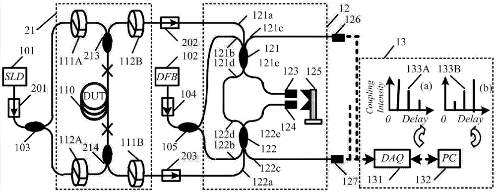
[0052] The measuring device is attached figure 2 shown, in addition to the test set 21 with the attached figure 1 Except that the test device 11 is different, the rest of the two devices are basically the same.

[0053] (1) The test device 21 includes a device under test 110, a forward coupler 213 and a reverse coupler 214 connected to both ends of the device under test 110, a first polarizer 111A and a first polarizer 111B, a first 2 polarizers 112A and a second analyzer 112B;

[0054] (2) The first coupler 213 and the second coupler 214 have the same physical parameters, and the two ends of the device under test 110 are respectively connected to one end of the forward coupler 213 and the reverse coupler 214; the first polarizer 111A and the second polarizer 112A respectively have the same physical parameters such as the polarizing angle, and the two are respectively connected to an input port of the first coupler 213 and the second coupler 214; the first polarizer 111B an...


PUM

PropertyMeasurementUnit
Wavelengthaaaaaaaaaa
Extinction ratioaaaaaaaaaa
Return lossaaaaaaaaaa

Abstract

The invention belongs to the technical field of optical fiber measurement, and particularly relates to a common-path forward-reverse simultaneous measuring device for a fiber optic gyroscope ring. The common-path forward-reverse simultaneous measuring device for the fiber optic gyroscope ring comprises a light source device, a testing device 11, an optical path correlator 12, and a photoelectric signal conversion and signal recording device 13, wherein the optical path correlator 12 consists of a first six-port coupler 121, a second six-port coupler 122, a first collimating lens 123, a second collimating lens 124 and a scanning table 125. By adopting the common-path forward-reverse simultaneous measuring device, the testing time of a fiber optic gyroscope ring polarization coupling measuring device is shortened, the measurement efficiency is improved, the influences of environmental factors such as temperature are eliminated, and the polarization coupling symmetry of the fiber optic gyroscope ring can be obtained accurately.

Description


Claims


Application Information

Patent Timeline
Owner HARBIN ENG UNIV
Why Eureka
Try Eureka