
Touch control display panel and touch control display device

A technology for touch display panels and display areas, which is applied in the direction of instruments, electrical digital data processing, and input/output processes of data processing, etc., and can solve the problem of weakening touch signals of touch electrodes, affecting touch sensitivity of touch display panels, Missing of touch drive electrodes and touch sense electrodes

Active Publication Date: 2017-10-24
XIAMEN TIANMA MICRO ELECTRONICS
View PDF7 Cites 70 Cited by
  • Summary
  • Abstract
  • Description
  • Claims
  • Application Information

AI Technical Summary

Problems solved by technology

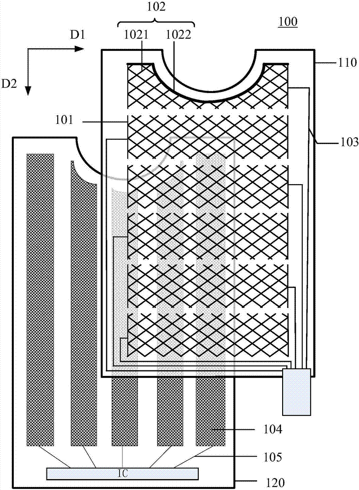
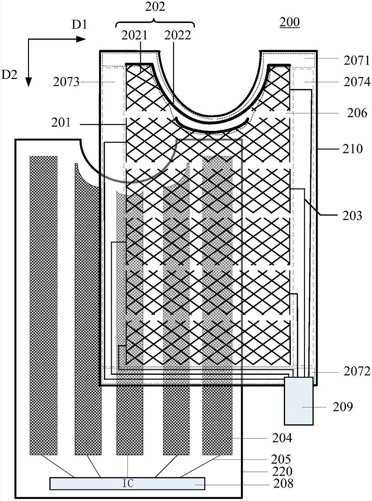
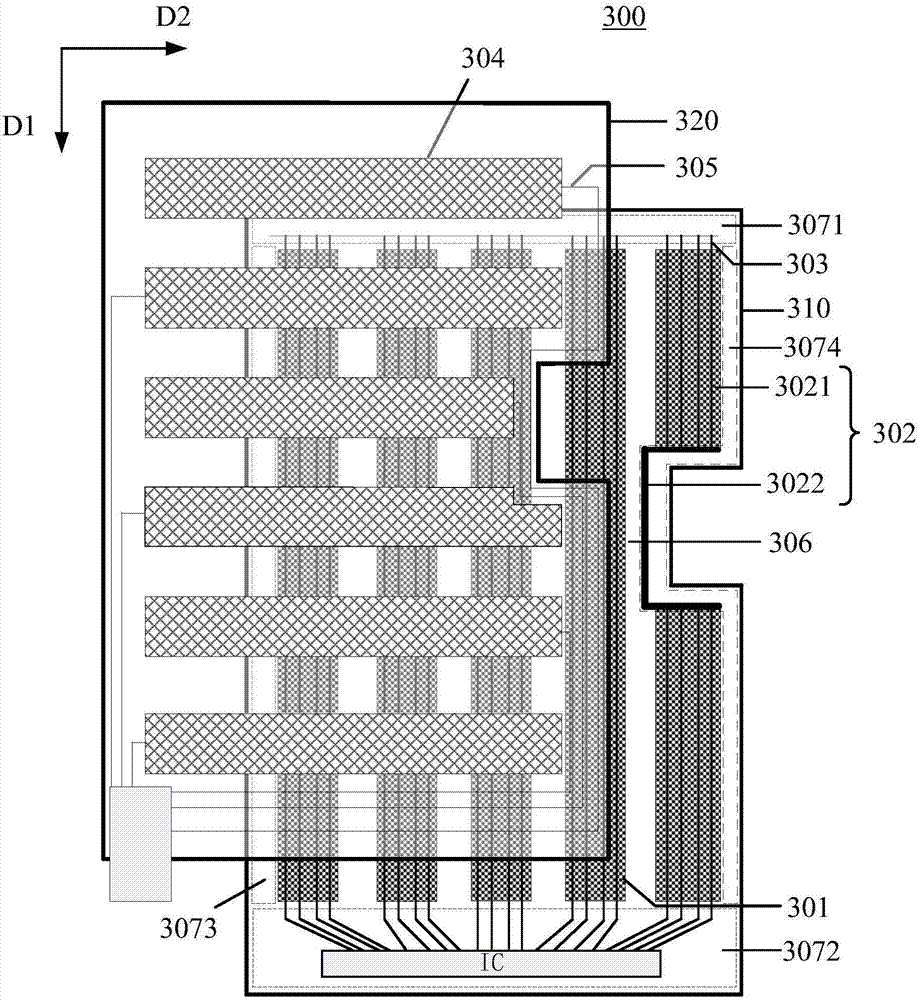
When the touch display panel is dug out to embed gaps in functional modules such as cameras, it usually results in the loss of some electrodes of the touch driving electrodes and touch sensing electrodes.
Furthermore, if a part of the touch driving electrode or touch sensing electrode located in the gap near the middle part of the electrode is missing, the resistance value of the touch driving electrode or touch sensing electrode will usually increase.
The increase of the resistance value of the touch electrode will lead to the weakening of the touch signal of the touch electrode, thereby affecting the touch sensitivity of the touch display panel.

Method used


Image

  • Touch control display panel and touch control display device
  • Touch control display panel and touch control display device
  • Touch control display panel and touch control display device

Examples


Embodiment Construction

[0014] The application will be further described in detail below in conjunction with the accompanying drawings and embodiments. It should be understood that the specific embodiments described here are only used to explain related inventions, rather than to limit the invention. It should also be noted that, for the convenience of description, only the parts related to the related invention are shown in the drawings.

[0015] It should be noted that, in the case of no conflict, the embodiments in the present application and the features in the embodiments can be combined with each other. The present application will be described in detail below with reference to the accompanying drawings and embodiments.

[0016] Please refer to figure 1 , which shows a schematic structural diagram of an embodiment of the touch display panel according to the present application. Such as figure 1 As shown, the touch display panel 100 of this embodiment may include a first substrate 110, a fir...


PUM


Abstract

The invention discloses a touch control display panel and a touch control display device. The touch control display panel comprises a first substrate; a plurality of touch control electrode strips disposed on the first substrate, wherein the plurality of first touch control electrode strips comprise a plurality of complete touch control electrode strips and at least one special-shaped touch control electrode strip, the area of each special-shaped touch control electrode strip is smaller than that of each complete touch control electrode strip, each special-shaped touch control electrode strip comprises an electrode portion and a metal wiring portion, and each metal wiring portion and the corresponding electrode portion of the same special-shaped touch control electrode strip are parallelly connected; and a plurality of first touch control signal lines, wherein each first touch control signal line is electrically connected with the corresponding first touch control electrode strip. According to the embodiment, through parallelly connecting the electrode portion and the metal wiring portion of each special-shaped touch control electrode strip, resistance of the special-shaped touch control electrode strip is reduced, signal strength of touch control signals of each special-shaped touch control electrode strip is enhanced, and touch control sensitivity of the touch control display panel is increased.

Description

technical field [0001] The present application relates to the field of display technology, in particular to a touch display panel and a touch display device including the touch display panel. Background technique [0002] With the rapid development of display technology, touch display technology has gradually pervaded people's lives. Among the existing touch display panels, compared with resistive touch display panels, capacitive touch display panels have the advantages of long life, high light transmittance, and support for multi-touch, and have become a hot spot in touch display technology. . Moreover, in order to meet the diverse needs of people, the existing touch display panel usually needs to cut the edge, and dig out a gap in the touch display panel that can be embedded with functional modules such as a camera. [0003] Existing touch display panels usually include touch driving electrodes and touch sensing electrodes intersecting. Mutual capacitance will be formed ...

Claims


Application Information

Patent Timeline
IPC IPC(8): G06F3/041G06F3/044
CPCG06F3/0412G06F3/044
Inventor 伍黄尧周洪波沈柏平
Owner XIAMEN TIANMA MICRO ELECTRONICS
Learn More