Engineering tool

A technology of engineering design tools and program modules, which is applied in the direction of calculation, program control, electrical program control, etc., and can solve problems such as time-consuming and time-consuming

Active Publication Date: 2017-10-24
MITSUBISHI ELECTRIC CORP
View PDF10 Cites 0 Cited by
  • Summary
  • Abstract
  • Description
  • Claims
  • Application Information

AI Technical Summary

Problems solved by technology

[0003] The above conventional method has the problem that it takes a lot of time for the user to operate from the execution of the control program to the confirmation.
In addition, in order to check the ope

Method used


Image

  • Engineering tool
  • Engineering tool
  • Engineering tool

Examples


Embodiment approach 1

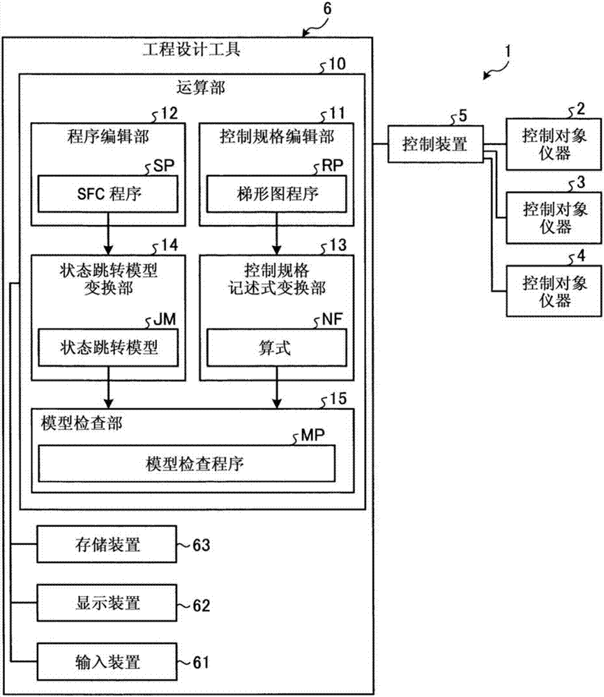
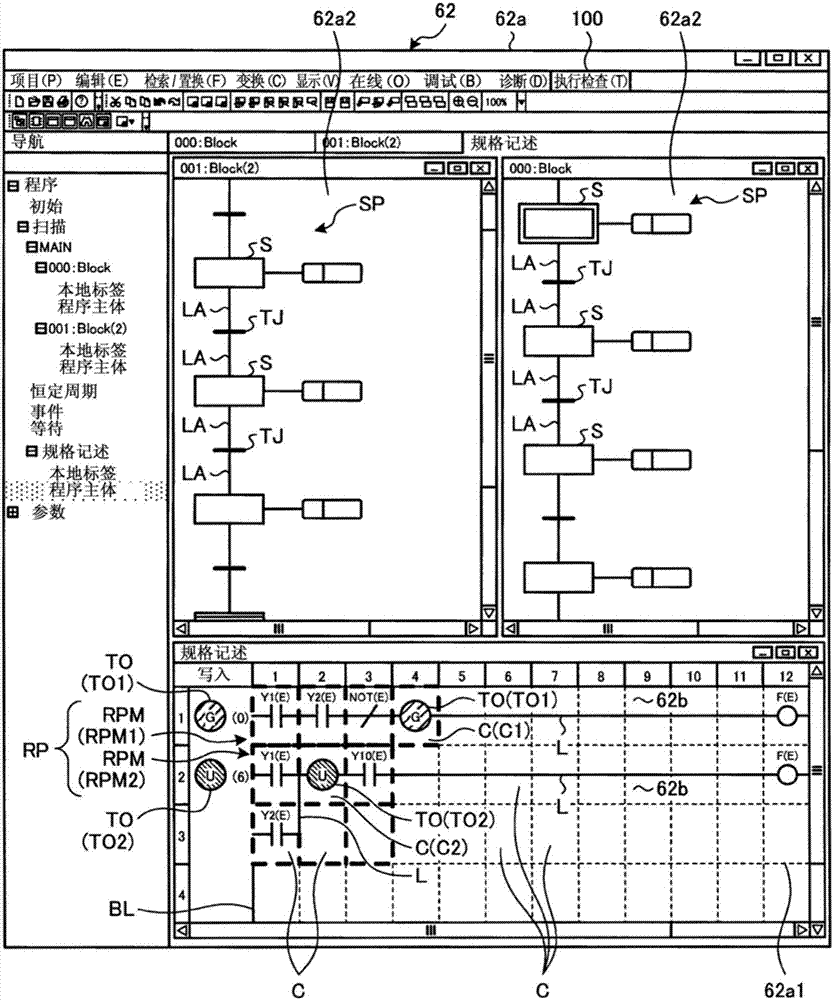
[0022] figure 1 It is a figure which shows the structure of the control system which the engineering design tool concerning Embodiment 1 has. figure 2 yes means figure 1 A diagram showing an example of a display screen of a display device of an engineering design tool. The control system 1 constitutes equipment in the field of FA (Factory Automation), such as figure 1 As shown, the control system 1 has: a plurality of control object instruments 2, 3, 4 arranged in the equipment; a control device 5 connected to the plurality of control object instruments 2, 3, 4; and an engineering design connected to the control device 5 tool6. The controlled devices 2, 3, and 4 are switches, regulating valves, solenoid valves, motors, or pumps installed in equipment, and are driving devices that perform operations. In Embodiment 1, the control system 1 has three control target devices 2, 3, 4, but may have a number other than three control target devices 2, 3, 4, and at least one control...


PUM


Abstract

An engineering tool is provided with a display area (62a1) displayed on a display screen (62a) of a display device (62) and displaying a ladder program (RP) and cells (C1) which are temporal-operator-assigned areas. The cells (C1) serving as the temporal-operator-assigned areas are areas to be displayed in the display area (62a1) and used for imparting temporal operators (TO1) to a program module (RPM1) of the ladder program (RP). The engineering tool is equipped with a control specification editing part and a control specification description type conversion part. The control specification editing part generates the program module (RPM1). The control specification description type conversion part converts the program module (RPM1) into a mathematical expression that can be input to a model inspection program.

Description

technical field [0001] The invention relates to an engineering tool for creating control programs. Background technique [0002] The operation confirmation of the control program using the existing engineering design tool is performed by connecting the engineering design tool to an actual controlled device or a simulator. Operation confirmation is usually performed by a method in which a control program desired to be confirmed is executed, and the state is monitored and confirmed by the user. In addition, in the operation confirmation, the initial value setting of the control program and the parameter setting at the time of execution are performed by inputting and setting by the user. [0003] The conventional method described above has a problem that it takes a lot of time for the user's operation from execution of the control program to confirmation. In addition, in the above-mentioned method, in order to check the operation in a list, the user needs to set the initial v...

Claims


Application Information

Patent Timeline
IPC IPC(8): G05B19/05
CPCG05B19/054G05B2219/13052G05B19/0426G05B2219/24034G06F3/0484G06F2203/04803
Inventor 山冈孝行滨崎弘
Owner MITSUBISHI ELECTRIC CORP
Why Eureka
Try Eureka