Lifting mechanism and range hood applying same

A lifting mechanism and a range hood technology, applied in the application, removal of oil fume, household stoves, etc., can solve the problems of the smoke guide plate moving not smoothly, poor user experience, etc., and achieve the effect of eliminating jitter and preventing weightlessness.

Inactive Publication Date: 2017-10-27
NINGBO FOTILE KITCHEN WARE CO LTD
View PDF7 Cites 11 Cited by
  • Summary
  • Abstract
  • Description
  • Claims
  • Application Information

AI Technical Summary

Problems solved by technology

Although the lifting and lowering of the smoke deflector can greatly improve the effect of oil absorption, but generally there is a phenomenon that the movement of the smoke deflector is not stable enough, and the user experience is poor.

Method used


Image

  • Lifting mechanism and range hood applying same
  • Lifting mechanism and range hood applying same
  • Lifting mechanism and range hood applying same

Examples


Embodiment 1

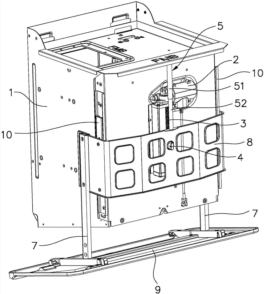
[0022] Such as figure 1 As shown, the lifting mechanism in this embodiment is installed on the range hood, and the lifting mechanism includes a mounting frame 1 , a driving motor 2 , a screw rod 3 and a nut 4 . Wherein, the fan housing constitutes the mounting frame 1, the driving motor 2 is installed on the mounting frame 1, the screw mandrel 3 is vertically arranged and rotates under the driving of the driving motor 2, and the nut 4 is installed on the screw mandrel 3. The range hood includes a fan cover, lifting rod 7, U-shaped connecting plate 8 and smoke guide plate 9, the lifting rod 7, U-shaped connecting plate 8 and smoke guiding plate 9 constitute the load of the lifting mechanism, and the load is installed on the nut 4 And with the nut for synchronous lifting movement.

[0023] The lifting mechanism includes a one-way damping device. When the lifting mechanism is in a descending state, the one-way damping device can generate a damping force on the screw rod 3 to off...

Embodiment 2

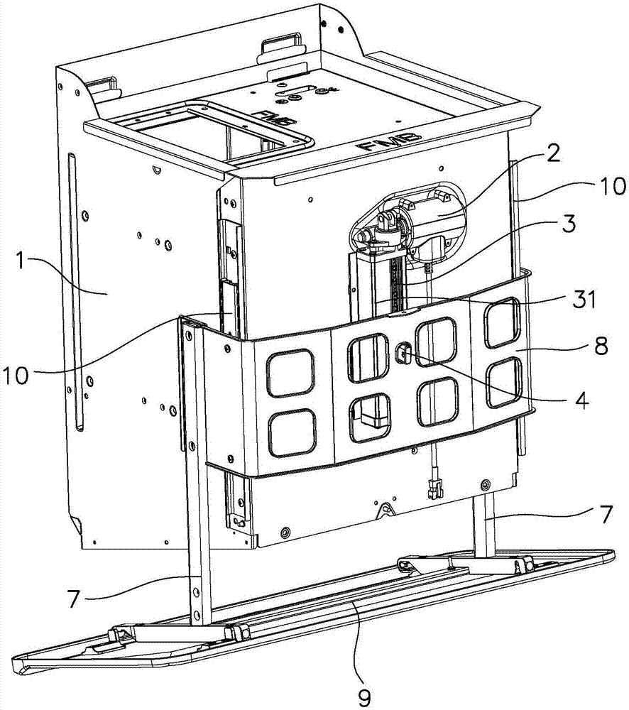
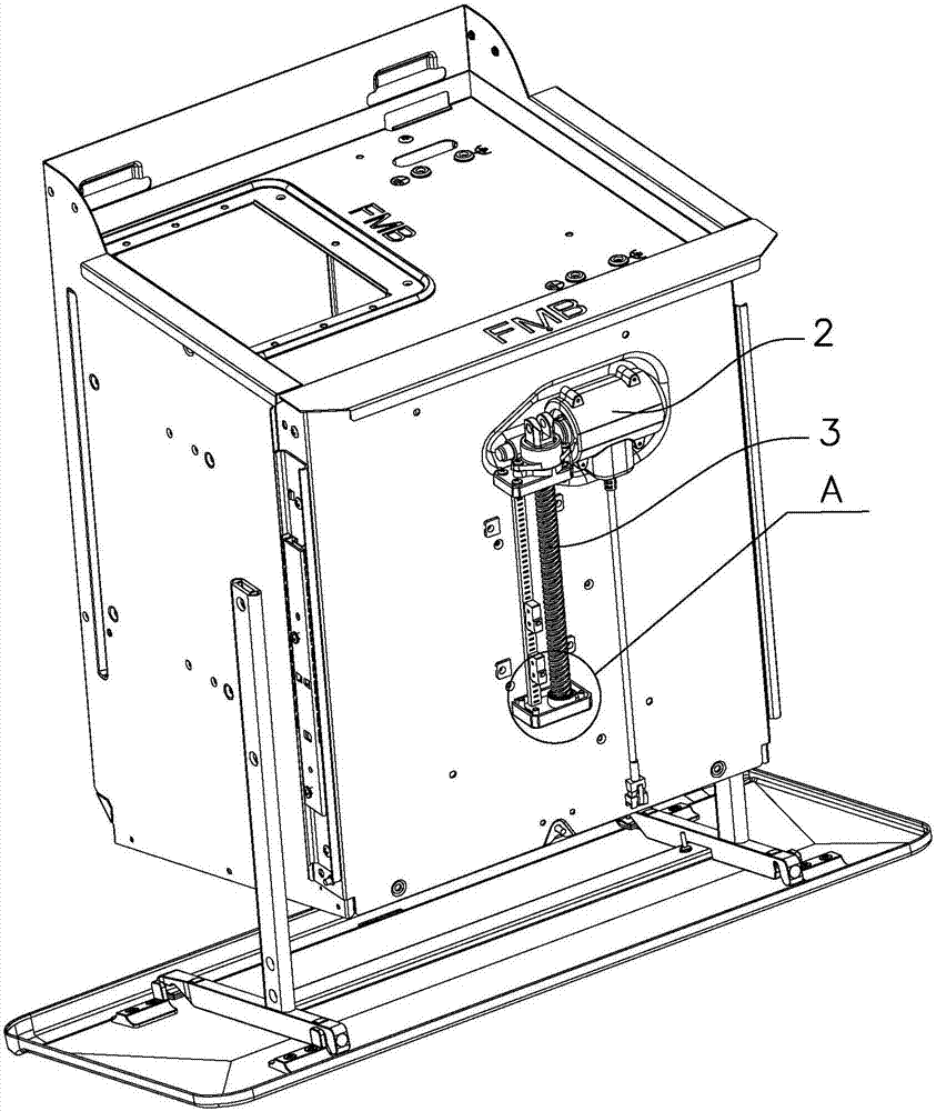
[0027] Such as Figure 2 to Figure 4 As shown, the one-way damping device of this embodiment adopts a one-way rotary damper 6, and the one-way rotary damper 6 is installed on the screw mandrel 3. Specifically, a screw mandrel protective cover 31 is installed outside the screw mandrel 3. The bottom of the screw mandrel protective cover 31 is provided with a screw mandrel mounting seat 32 , and the one-way rotation damper 6 is arranged in the screw mandrel mounting seat 32 .

[0028] When working, when the lifting mechanism rises, the one-way rotation damper 6 does not generate a damping force, and when it descends, it generates a damping force on the screw rod 3. This damping force can just eliminate the influence of the gravity of the load end on the screw rod, so that the mechanism can operate under load. When descending, it will not be in the state of "weightlessness", avoiding the resulting vibration and abnormal sound, and then helping the smoke deflector 9 to maintain a s...


PUM


Abstract

The invention discloses a lifting mechanism. The lifting mechanism comprises an installation frame, a driving motor, a screw rod and a nut, wherein the driving motor is arranged on the installation frame; the screw rod is driven by the driving motor to rotate; the nut is arranged on the screw rod; a load of the lifting mechanism is installed on the nut and does synchronous lifting motion along with the nut. The lifting mechanism is characterized by also comprising a one-way damping device, wherein under the falling state of the lifting mechanism, the one-way damping device can generate a damping force to the screw rod, and the damping force is used for offsetting and eliminating the influence of the load on the screw rod. The invention also discloses a range hood adopting the lifting mechanism. The lifting mechanism and the range hood disclosed by the invention have the advantages that the lifting mechanism adopts a screw-rod and nut mechanism, the load is installed on the nut and does synchronous lifting motion along with the nut, the one-way damping device can generate a damping force to the screw rod, and the damping force is used for offsetting and eliminating the influence of the load on the screw rod, so that the jittering and abnormal noise in the motion process of the lifting mechanism can be eliminated, and the unstable phenomenon of weightlessness caused by self weight of the load in the falling process of the mechanism is avoided.

Description

technical field [0001] The invention relates to a range hood, in particular to a lifting mechanism and a range hood using the lifting mechanism. Background technique [0002] There are many existing lifting mechanisms, such as the common screw nut mechanism, which mainly includes two components that cooperate with each other, the screw and the nut. Usually, the load is installed on the nut, and the nut and the load can be driven by the rotation of the screw. Corresponding movement along the screw rod. As we all know, the helix angle of the screw directly affects the performance of the screw nut mechanism. If the helix angle is large, although the motor speed requirement is low, the self-locking ability of the mechanism is poor, and it is easy to cause load slippage; if the helix The lift angle is small, although the self-locking ability of the mechanism is strong, and the load is not easy to slide, but the requirement for the motor speed is high, and the increase of the mot...

Claims


Application Information

Patent Timeline
Patent Type & Authority Applications(China)
IPC IPC(8): F24C15/20
CPCF24C15/20
Inventor 张静叶丰茅忠群诸永定申志贤
Owner NINGBO FOTILE KITCHEN WARE CO LTD
Why Eureka
Try Eureka