
Distributed fiber laying method

A distributed optical fiber and optical fiber technology, applied in the direction of optical devices, measuring devices, instruments, etc., can solve the problems of difficult to achieve resolution and increase the cost of monitoring systems, and achieve the effects of simple laying process, easy promotion and utilization, and convenient construction

Inactive Publication Date: 2017-10-27
FASTEN HONGSHENG GRP CO LTD
View PDF3 Cites 10 Cited by
  • Summary
  • Abstract
  • Description
  • Claims
  • Application Information

AI Technical Summary

Problems solved by technology

However, in practical applications, the mixed use of multiple sensors or the improvement of hardware facilities will significantly increase the cost of the monitoring system
[0004] At present, most of the conventional methods of laying distributed optical fibers are laid directly along the measured object in one-dimensional direction, which is simple and efficient; however, when the surface of the measured object is large and the monitoring requires high spatial resolution, this This one-dimensional laying method is difficult to achieve the required resolution, and it is urgent to improve it

Method used


Image

  • Distributed fiber laying method
  • Distributed fiber laying method
  • Distributed fiber laying method

Examples


Embodiment Construction

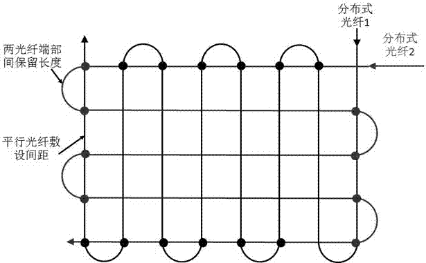
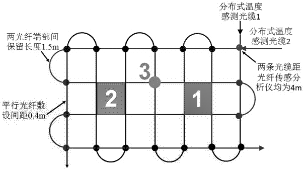
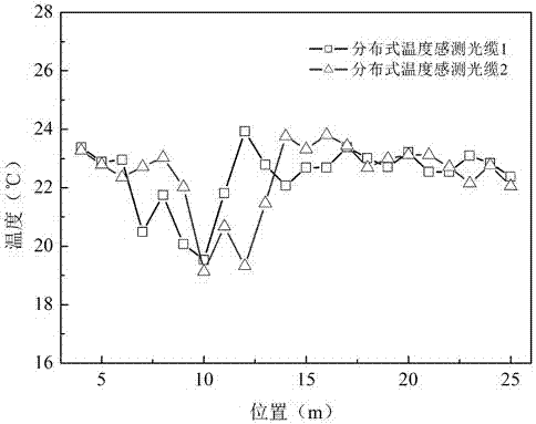
[0032] see figure 1 ~3, a kind of distributed optical fiber laying method that the present invention relates to, described method comprises the following steps:

[0033] Step 1. Determine the spatial resolution required for monitoring (spatial resolution is mainly determined according to the accuracy required by the monitored object, that is, customized according to monitoring requirements or accuracy, and this value is predefined data);

[0034] Step 2. Calculate the side length of the grid structure according to the spatial resolution determined in step A (when the spatial resolution is a×b, the side lengths of the grid are respectively k×a×b; where k is a constant coefficient, generally k=1);

[0035] Step 3. Laying of horizontally distributed optical fibers: laying horizontally distributed optical fibers into a horizontal serpentine coiled structure, the horizontal serpentine coiled structure is composed of a plurality of parallel horizontal straight segments, and the sam...


PUM

PropertyMeasurementUnit
lengthaaaaaaaaaa

Abstract

The invention discloses a distributed fiber laying method, and the method comprises the steps: 1, determining the spatial resolution required by the monitoring; 2, calculating the side length of a network structure according to the spatial resolution determined at step 1; 3, carrying out the laying of lateral distributed fibers; 4, carrying out the laying of longitudinal distributed fibers; 5, enabling the ports of the lateral distributed fibers and longitudinal distributed fibers to be connected to an optical fiber sensing analyzer. The method provided by the invention is high in resolution.

Description

technical field [0001] The invention relates to a monitoring method for a distributed optical fiber sensing system, in particular to a method for laying optical fibers used in a distributed optical fiber sensing system, and belongs to the field of optical fiber technology. Background technique [0002] The monitoring principle of the distributed optical fiber sensing system is: at the same time, the optical fiber is used as the sensing sensitive element and the transmission signal medium, and the advanced OTDR technology is used to detect the temperature and strain changes at different positions along the optical fiber, so as to realize the truly distributed Measurement. The distributed optical fiber sensing system is a new type of detection system for real-time measurement of temperature or stress distribution. It has the advantages of long measurement distance, high measurement accuracy, accurate positioning, fast response speed, and flexible alarm methods. In recent year...

Claims


Application Information

Patent Timeline
Patent Type & Authority Applications(China)
IPC IPC(8): G01B11/16G01K11/32
CPCG01B11/16G01K11/32
Inventor 刘礼华郑锐张昶阳宁强陆骁旻赵霞邵强华苏武徐国庆
Owner FASTEN HONGSHENG GRP CO LTD
Learn More