Electronic tag and electronic tag-based power management method and apparatus

A technology of electronic tags and power management modules, which is applied in the field of electronic tags, can solve problems such as the inability to control the voltage of electronic tag loads, and achieve the effect of improving stability and work efficiency

Inactive Publication Date: 2017-10-27
ZTE CORP
View PDF5 Cites 1 Cited by
  • Summary
  • Abstract
  • Description
  • Claims
  • Application Information

AI Technical Summary

Problems solved by technology

[0006] The present invention provides an electronic tag, a power management method of the electronic tag, a device method and a device, so as to at least solve the problem in the related art that the voltage of the load in the electronic tag cannot be controlled

Method used


Image

  • Electronic tag and electronic tag-based power management method and apparatus
  • Electronic tag and electronic tag-based power management method and apparatus
  • Electronic tag and electronic tag-based power management method and apparatus

Examples


Embodiment 1

[0035] An electronic tag is also provided in this embodiment. As used below, the term "module" may be a combination of software and / or hardware that realizes a predetermined function. Although the devices described in the following embodiments are preferably implemented in software, implementations in hardware, or a combination of software and hardware are also possible and contemplated.

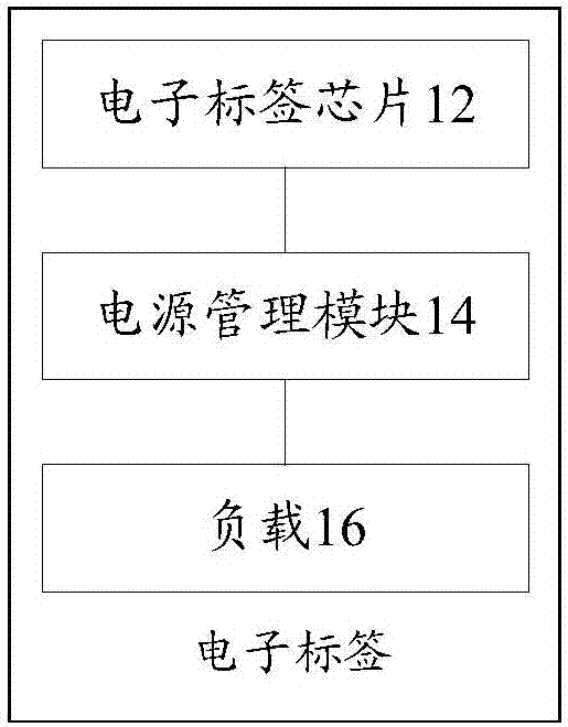
[0036] figure 1 is a structural block diagram of an optional electronic tag according to an embodiment of the present invention, such as figure 1 As shown, the electronic tag includes: an electronic tag chip 12, a power management module 14 and a load 16, wherein,

[0037] 1) The electronic tag chip 12 is used to instruct the load 16 to execute the instructions received by the electronic tag chip 12;

[0038] 2) The power management module 14 is connected to the electronic label chip 12, and the power management module 14 is used to control the voltage of the load 16;

[0039] 3) The loa...

Embodiment 2

[0077] In this embodiment, a power management method for an electronic tag is provided, Figure 10 is a flowchart of an optional power management method for an electronic tag according to an embodiment of the present invention, such as Figure 10 As shown, the process includes the following steps:

[0078] Step S1002, instructing the load to execute the instruction received by the electronic label chip through the electronic label chip;

[0079] Step S1004, controlling the voltage of the load through the power management module;

[0080] Step S1006, executing the instruction received by the electronic tag chip through the load.

[0081] Optionally, the above-mentioned power management method for an electronic tag may be applied to, but not limited to, a radio frequency identification scenario. For example: the scenario where the load in the electronic tag is controlled by the tag reader / writer.

[0082] Optionally, the above-mentioned power management method of an electron...

Embodiment 3

[0092] This embodiment also provides a power management device for an electronic tag, the device is used to implement the above embodiments and preferred implementations, and what has been described will not be repeated. As used below, the term "module" may be a combination of software and / or hardware that implements a predetermined function. Although the apparatus described in the following embodiments is preferably implemented in software, implementations in hardware, or a combination of software and hardware, are also possible and contemplated.

[0093] Figure 11 is a structural block diagram of an optional electronic tag power management device according to an embodiment of the present invention, such as Figure 11 As shown, the device includes:

[0094] 1) the instruction module 112, used for instructing the load to execute the instruction received by the electronic tag chip through the electronic tag chip;

[0095] 2) the control module 114, coupled to the indication...


PUM


Abstract

The invention provides an electronic tag and an electronic tag-based power management method and apparatus. The electronic tag comprises an electronic tag chip, a power management module and a load, wherein the electronic tag chip is used for instructing a load to execute an instruction received by the electronic tag chip; the power management module is connected with the electronic tag chip and used for controlling a voltage of the load; and the load is connected with the power management module and used for executing the instruction received by the electronic tag chip according to the instruction of the electronic tag chip. Through the electronic tag and the power management method and apparatus, the problem that the voltage of the load in the electronic tag cannot be controlled in related technologies is solved; and the control on the voltage of the load in the electronic tag is realized.

Description

technical field [0001] The present invention relates to the field of communications, and in particular, to an electronic tag, a power management method and device for the electronic tag. Background technique [0002] The Internet of Things (Internet of Things) is simply the extension of the Internet from people to things. huge network. Its purpose is to allow items to be connected to the network to facilitate the identification and management of items. In the Internet of Things, the key component is the radio frequency identification electronic tag tied to the item. According to different applications, RFID electronic tags include not only the usual devices such as electronic tag chips and antennas, but also various sensors, optical displays and other loads. Although loads such as sensors and optical displays are low-power devices, compared with the power consumption of the usual electronic tag chips, the power consumption of loads such as sensors and optical displays is ...

Claims


Application Information

Patent Timeline
Patent Type & Authority Applications(China)
IPC IPC(8): G06K19/07
CPCG06K19/0704G06K19/0708G06K19/0716G06K19/07
Inventor 张灏文陈新安
Owner ZTE CORP
Why Eureka
Try Eureka