Lifting type cake frame separable from mechanical operator

A motorized device and lift-type technology, applied in display hangers, display shelves, display stands, etc., can solve problems such as malfunction, inconvenient cleaning and washing, etc.

Inactive Publication Date: 2017-10-31
沈永培
View PDF0 Cites 11 Cited by
  • Summary
  • Abstract
  • Description
  • Claims
  • Application Information

AI Technical Summary

Problems solved by technology

In the past two years, I designed and produced two lifting cakes. Because the limit switch that controls the lifting is installed on the edge of the cake pan, it will fail if it is moved during transportation.
In addition, the wire connection cannot be removed from the cake pan, making cleaning very inconvenient

Method used


Image

  • Lifting type cake frame separable from mechanical operator
  • Lifting type cake frame separable from mechanical operator
  • Lifting type cake frame separable from mechanical operator

Examples


Embodiment Construction

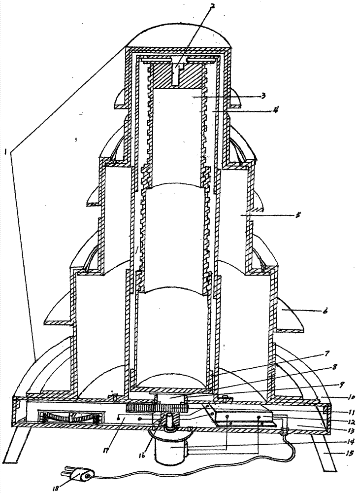
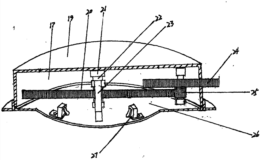
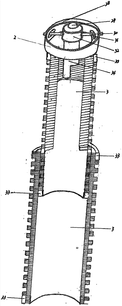
[0011] exist figure 1 The cake stand (1) in is a liftable cake stand that can be separated from the motorized device. The middle part of the cake stand (1) is a sleeve screw rod (3) made of ABS engineering plastics, and a shaking device (2) is installed at the top of the sleeve screw rod (3). Outside the sleeve screw (3), there is a set made of aluminum, which can absorb the sway produced by the sleeve screw (3) during the rotation and lifting process through the shake elimination device (2) and absorb the stability in the stabilization sleeve. The cover (4) is fixed together with the top surface of the stabilizer (2) with screws on the top surface of the stabilizer (4), and the bottom of the stabilizer (4) is fixed on the chassis cover (10) of the cake stand . The lifting tower (5) is nested flexibly outside the stabilizing cover (4), and the cake pan (6) made of food-grade non-toxic plastic or metal material is nested on the lifting tower (5). At the bottom of the sleeve ...


PUM


Abstract

A "lifting cake stand that can be separated from the motor device" is a mechanically stable cake stand that is designed and applied with a gear limiter with a rated motor revolution to control the lift, especially a cake stand that can be clamped in layers The garland is not only beautiful, but also a novel food appliance that can be used repeatedly by easily removing the cake pan for cleaning.

Description

Technical field: [0001] The invention relates to a food appliance, especially a "lifting cake stand that can be separated from the motor device" that uses a gear stopper to control the lifting, can isolate food from the machine and can be removed for cleaning. Background technique: [0002] Layered cakes have always been static. In the past two years, I designed and produced two types of lifting cakes. Because the limit switch for controlling the lifting is installed on the edge of the cake pan, it will fail if it is moved during transportation. In addition, the wire connection cannot be removed from the cake pan, making cleaning and scrubbing very inconvenient. Invention content: [0003] The present invention provides a gear-type limiter that controls the number of revolutions of the motor to control the lifting performance of the cake stand. Cake stand" to solve the above problems. The specific scheme adopted by the present invention to solve the technical problems o...

Claims


Application Information

Patent Timeline
Patent Type & Authority Applications(China)
IPC IPC(8): A47F5/06A47F7/00
CPCA47F5/06A47F7/00A47F7/0007
Inventor 沈永培
Owner 沈永培
Why Eureka
Try Eureka