Large-diameter piston switch structure of high-dynamic-pressure shock tube

A technology of switch structure and shock tube, applied in the direction of mechanical equipment, circuit components, etc., can solve the problems of long cycle, heavy diaphragm workload, and difficulty in realizing a single diaphragm.

Active Publication Date: 2021-02-05
中国人民解放军军事科学院国防工程研究院工程防护研究所
View PDF5 Cites 0 Cited by
  • Summary
  • Abstract
  • Description
  • Claims
  • Application Information

AI Technical Summary

Problems solved by technology

[0002] At present, most commonly used shock tubes use a single diaphragm installed between the driving section and the driven section to separate the driving section from the driven section. , the compressed gas in the driving section expands outward, forming a preset shock wave environment in the driven section; however, it is difficult to realize a single diaphragm for a large high-pressure shock tube, and the replacement of the diaphragm when using a multi-stage multi-diaphragm structure requires a large workload and a long cycle , we must find another way

Method used


Image

  • Large-diameter piston switch structure of high-dynamic-pressure shock tube
  • Large-diameter piston switch structure of high-dynamic-pressure shock tube
  • Large-diameter piston switch structure of high-dynamic-pressure shock tube

Examples


Embodiment Construction

[0030] The present invention will be further described with reference to the drawings and specific embodiments, but not limited to the following embodiments.

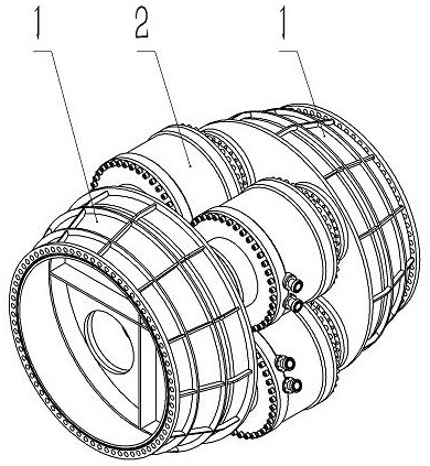
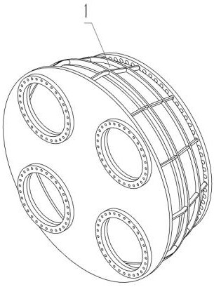
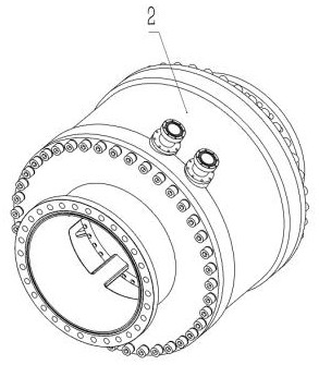
[0031] Such as figure 1 As shown, a large-diameter piston switch structure of a high dynamic pressure shock tube, the large-diameter piston switch structure is connected between the body of the shock tube driving section and the body of the shock tube driven section; it is mainly composed of a pair of transition connectors 1. Composed of four single-piston switches 2; the four single-piston switches 2 are located in the same plane, and are evenly distributed and fixedly connected between the pair of transition connectors 1; as figure 2 As shown, the transition connector 1 has a through hole at the junction with the single piston switch 2; the total diameter of the through hole on the transition connector 1 is greater than or equal to the total diameter of the plurality of single piston switches 2 .

[0032] Such as ...


PUM


Abstract

The invention belongs to the technical field of development of high-dynamic-pressure shock tubes, and provides a large-diameter piston switch structure of a high-dynamic-pressure shock tube. The large-diameter piston switch structure is provided with a plurality of single-piston switches located in the same plane; each single-piston switch is provided with a high-pressure cylinder barrel formed bysleeving an inner pipe body with an outer pipe body; the outer pipe body is fixedly connected between a high-pressure cylinder upper opening end cover and a high-pressure cylinder lower opening end cover in a sealed mode. the outer pipe body of the high-pressure cylinder barrel is connected with an air inlet barrel/air outlet barrel; the inner tube body is hermetically connected with an upper opening adapter tube connected with the shock tube driving section tube body; a piston capable of freely sliding along the inner wall of the inner pipe body is arranged in the inner pipe body; an auxiliary air pressure chamber is formed by the piston, an inner barrel body and the upper opening adapter tube; the auxiliary air pressure chamber is communicated with the air inlet barrel/air outlet barrelthrough an air inlet/air outlet through hole in the upper opening adapter tube, opening and closing of the piston can be achieved by adjusting the pressure in the auxiliary air pressure chamber, andtherefore connection or disconnection of the shock tube driving section tube body and the shock tube driven section tube body is achieved. The structure has the advantages of being rapid in piston opening, capable of being repeatedly used, high in controllability, efficient and safe.

Description

technical field [0001] The invention belongs to the technical field of high dynamic pressure shock tube development, and in particular relates to a large-diameter piston switch structure of a high dynamic pressure shock tube, which is used for simulating the shock wave environment produced by the explosion of different equivalent charges. Background technique [0002] At present, most commonly used shock tubes use a single diaphragm installed between the driving section and the driven section to separate the driving section from the driven section. , the compressed gas in the driving section expands outward, forming a preset shock wave environment in the driven section; however, it is difficult to realize a single diaphragm for a large high-pressure shock tube, and the replacement of the diaphragm when using a multi-stage multi-diaphragm structure requires a large workload and a long cycle , we must find another way. Contents of the invention [0003] In order to solve th...

Claims


Application Information

Patent Timeline
Patent Type & Authority Applications(China)
IPC IPC(8): F15C1/00F15C1/02F15C1/20
CPCF15C1/005F15C1/02F15C1/20
Inventor 任辉启吴飚刘国强周松柏汪剑辉王世合黄魁郭良赵强王幸
Owner 中国人民解放军军事科学院国防工程研究院工程防护研究所
Why Eureka
Try Eureka