
Control method and device of strip head and strip tail centering cameras of laser welding machine

A laser welding machine and control method technology, applied in laser welding equipment, welding equipment, manufacturing tools, etc., can solve the problems of inability to distinguish secondary shear edge wires, strip deviation, etc., to prevent inaccurate detection data, The effect of eliminating interference and avoiding deviation

Active Publication Date: 2017-11-03
SHOUGANG JINGTANG IRON & STEEL CO LTD
View PDF6 Cites 1 Cited by
  • Summary
  • Abstract
  • Description
  • Claims
  • Application Information

AI Technical Summary

Problems solved by technology

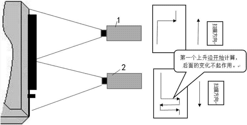
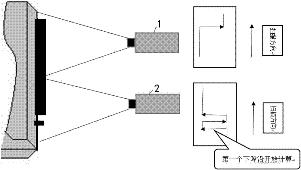
[0006] The present invention provides a control method and device for the centering camera of the head and tail of the laser welding machine, which solves the technical problem in the prior art that the secondary shearing side wire cannot be distinguished during centering, resulting in strip steel deviation

Method used


Image

  • Control method and device of strip head and strip tail centering cameras of laser welding machine
  • Control method and device of strip head and strip tail centering cameras of laser welding machine
  • Control method and device of strip head and strip tail centering cameras of laser welding machine

Examples


Embodiment 1

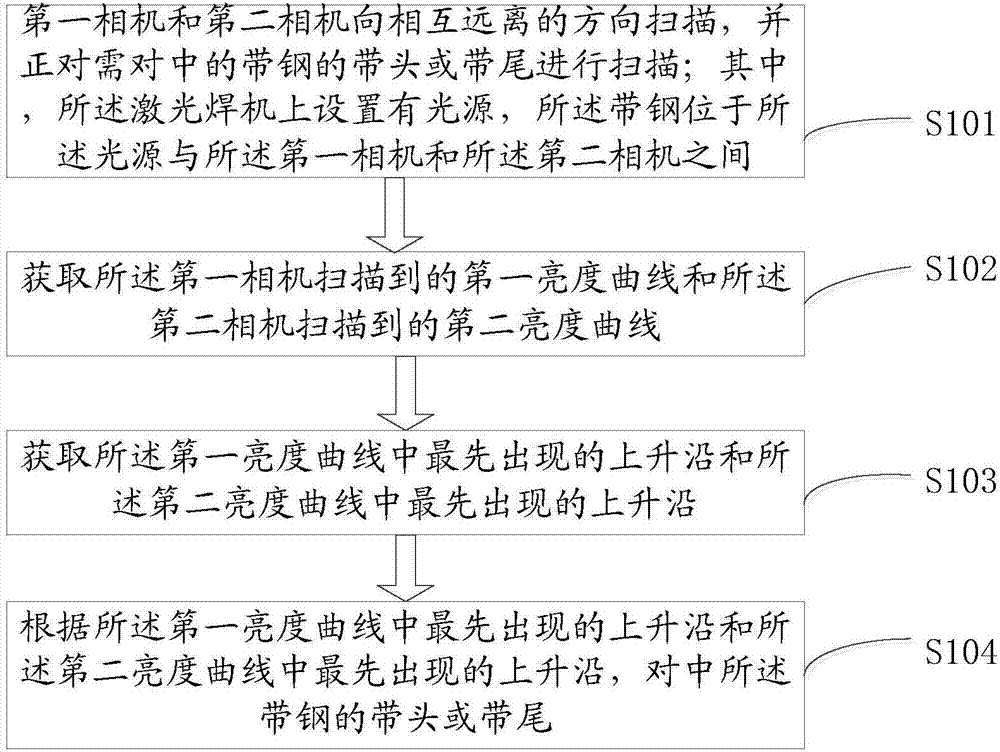
[0043] In this embodiment, a control method of a laser welding machine with a head and a tail centering camera is provided, such as figure 1 Shown include:

[0044] Step S101, the first camera and the second camera scan in a direction away from each other, and scan the head or tail of the steel strip to be aligned; wherein, the laser welding machine is provided with a light source, and the steel strip between the light source and the first and second cameras;

[0045] Step S102, acquiring a first brightness curve scanned by the first camera and a second brightness curve scanned by the second camera;

[0046] Step S103, acquiring the first rising edge in the first brightness curve and the first rising edge in the second brightness curve;

[0047] Step S104, centering the strip head or strip tail according to the first rising edge in the first brightness curve and the first rising edge in the second brightness curve.

[0048] It should be noted that a light source is provided o...

Embodiment 2

[0081] This embodiment provides a control device for a laser welding machine with a head and a tail centering camera, such as Figure 4 shown, including:

[0082] The scanning module 401 is used to control the first camera and the second camera to scan in a direction away from each other, and is scanning the head or tail of the steel strip to be centered; wherein, the laser welder is provided with a light source, the strip is located between the light source and the first and second cameras;

[0083] A curve acquiring module 402, configured to acquire a first brightness curve scanned by the first camera and a second brightness curve scanned by the second camera;

[0084] A rising edge acquisition module 403, configured to acquire the first rising edge in the first brightness curve and the first rising edge in the second brightness curve;

[0085] The centering module 404 is configured to center the strip head or strip tail according to the first rising edge in the first brig...


PUM


Abstract

The invention discloses a control method and device of strip head and strip tail centering cameras of a laser welding machine. The control method comprises the steps that the first camera and the second camera scan in the opposite directions and right face the strip head or the strip tail of strip steel to be centered for scanning; a first luminance curve scanned by the first camera and a second luminance curve scanned by the second camera are obtained; the rising edge which is initially appeared in the first luminance curve and the rising edge which is initial appeared in the second luminance curve are obtained; and according to the rising edge which is initially appeared in the first luminance curve and the rising edge which is initially appeared in the second luminance curve, the strip head or the strip tail of the strip steel is centered. The technical problem that in the prior art, secondary cutting edge wires cannot be distinguished during centering, and consequently, the strip steel deviates is solved. The technical effects that interference of the secondary cutting edge wires is eliminated completely, labor for removing the edge wires is omitted, and the production quality is improved are achieved.

Description

technical field [0001] The invention belongs to the technical field of automatic control of cold rolling, and in particular relates to a control method and device for a head and tail centering camera of a laser welding machine. Background technique [0002] According to the requirements of the continuous annealing and galvanizing production process, the front and rear alignment of the strip steel must be ensured after the welding of the lead and tail of the plate is completed, so as to ensure that the strip steel near the weld seam does not deviate in the production line. At present, the alignment of the steel strip is mainly ensured by the camera centering actuator. According to the strip steel data detected by camera scanning, it is judged whether the strip steel is in the center of the clamp. If the strip is no longer in the center position, the strip is clamped by a small clamp to move the position to center. [0003] In the normal production process, in order to ensur...

Claims


Application Information

Patent Timeline
Patent Type & Authority Applications(China)
IPC IPC(8): B23K26/03B23K26/082
CPCB23K26/03B23K26/082
Inventor 孟祥顺刘冀川韩明杨红远王元奎苏晓蒙陈亮李川付友昌戚金超吕剑王彬赵坤鹏
Owner SHOUGANG JINGTANG IRON & STEEL CO LTD
Learn More