Flexible mechanical arm with buffering function

A manipulator and flexible finger technology, applied in the field of flexible manipulators, can solve the problems of complicated pipeline connection, strength limitation, and easy failure of flexible manipulators, and achieve the effect of increasing the application range and reducing the accuracy requirements.

Pending Publication Date: 2017-11-03
SUZHOU ROROBOT TECH CO LTD
View PDF9 Cites 29 Cited by
  • Summary
  • Abstract
  • Description
  • Claims
  • Application Information

AI Technical Summary

Problems solved by technology

[0004] 1. At present, each flexible finger of the flexible manipulator is externally connected to the air pipe and the main air intake pipe. Therefore, the entire pipeline connection is complicated, and installation and maintenance are difficult. In some harsh environments, the above-mentioned flexible manipulator is prone to failure. low reliability
[0005] 2. Since the tail of the current flexible fingers is set as a tapered air inlet, taking the flexible fingers placed vertically as an example, the upper part of each flexible finger is a tapered air inlet, and the tapered air inl

Method used


Image

  • Flexible mechanical arm with buffering function
  • Flexible mechanical arm with buffering function
  • Flexible mechanical arm with buffering function

Examples


Embodiment 1

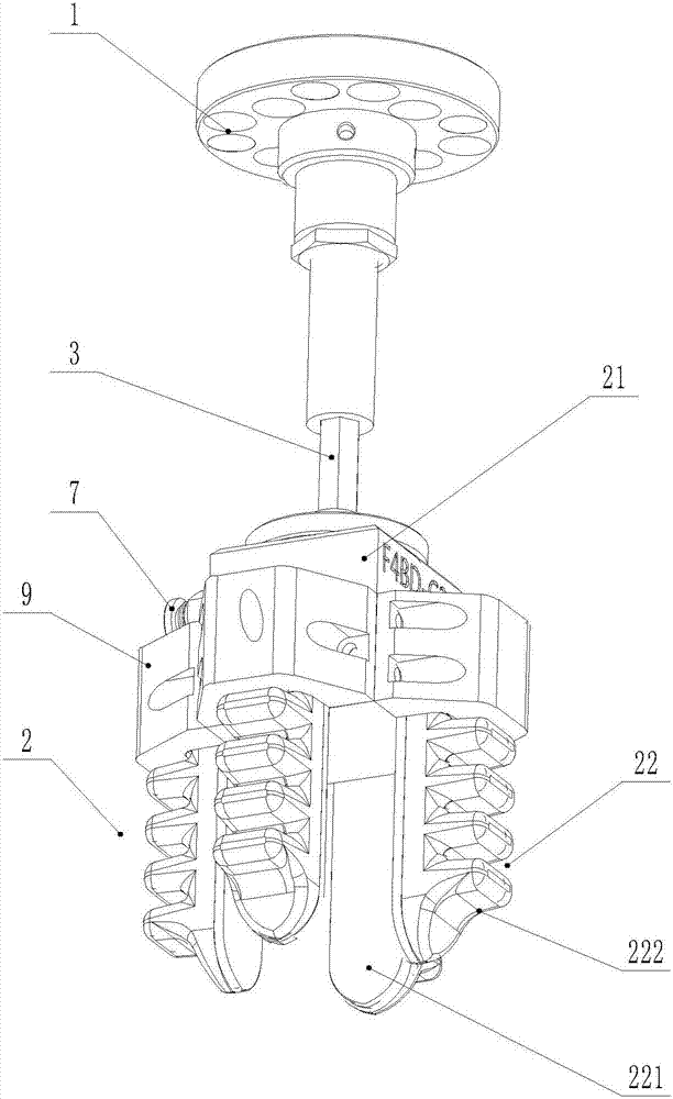
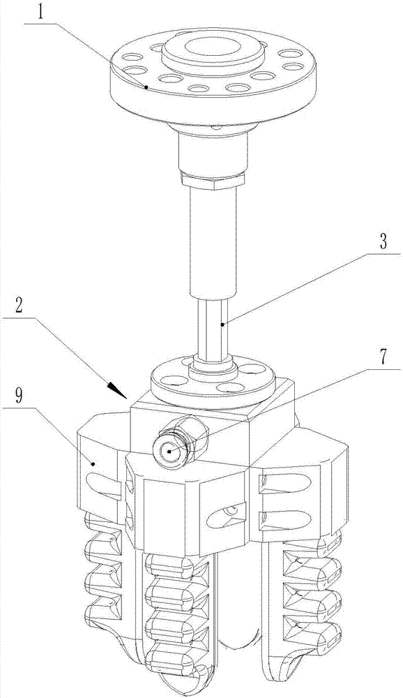
[0040] Such as Figures 1 to 10 As shown, a flexible manipulator with cushioning function includes a flexible manipulator body 2 and a mounting flange 1, and the flexible manipulator also includes an elastic buffer assembly installed between the flexible manipulator body 2 and the mounting flange 1 The space is used to elastically change the distance between the installation flange 1 and the flexible manipulator body 2. The flexible manipulator body 2 includes an integrated block 21, and at least two flexible fingers 22 that cooperate with each other to achieve flexible clamping are installed on the integrated block 21. , the flexible finger 22 includes a finger bottom plate 221 and a finger finger surface 222, the finger bottom plate 221 and the finger finger surface 222 together form a drive chamber, and the elastic modulus of the finger bottom plate 221 is greater than that of the finger finger surface 222 modulus, each flexible finger 22 is provided with an air vent 223 co...

Embodiment 2

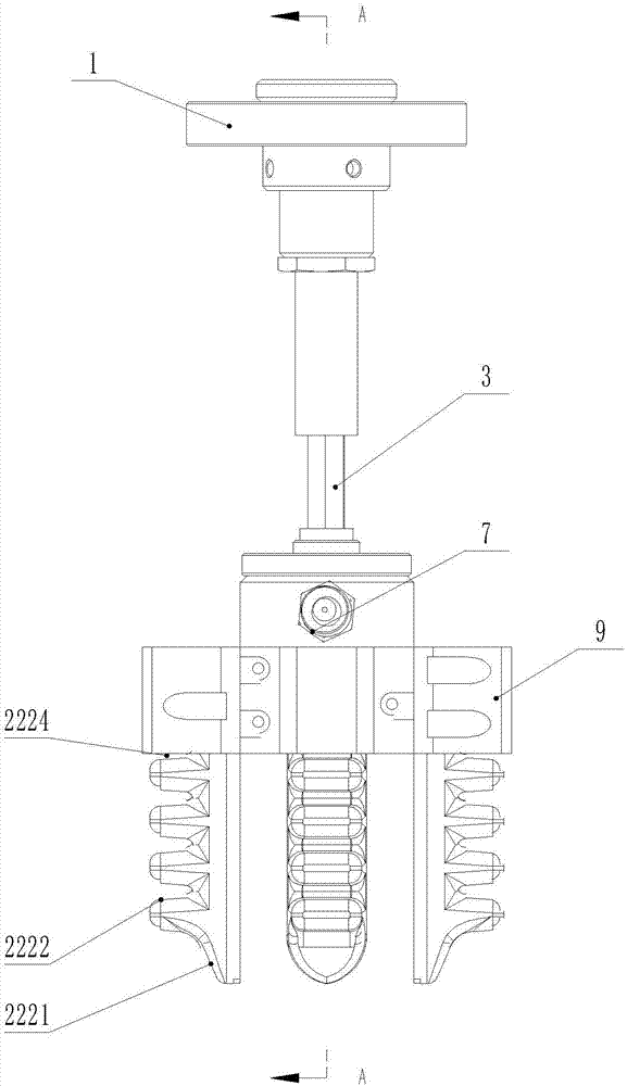
[0047] Such as Figure 8-10 As shown, the finger segment 2222 is wave-shaped, and at least one group of reinforcing ribs is arranged in the driving chamber, and the group of reinforcing ribs includes the rib body 12 equal to the number of troughs of the finger segment 2222. The reinforcing rib The body 12 is connected one by one between the inner sidewall of the trough of the finger segment 2222 and the finger bottom plate 221. The rib body 11 can improve the compressive strength of the flexible finger and prolong the service life. The rib body 12 does not affect the gas flow. flow.

[0048] Other technical features in Embodiment 2 are similar to those in Embodiment 1, and will not be repeated here.

Embodiment 3

[0050] Such as Figure 11 As shown, the knuckle segment 2222 is wave-shaped, and the bottom of the trough of the knuckle segment 2222 is provided with a reinforcing sheet 11, and at least one set of reinforcing ribs is also provided in the driving chamber, and the set of reinforcing ribs includes a knuckle. There are rib bodies 12 equal in number to the troughs of the segment 2222 , and the rib bodies 12 are connected between the inner sidewall of the trough bottom of the finger segment 2222 and the finger bottom plate 221 in one-to-one correspondence.

[0051] Other technical features in Embodiment 3 are similar to those in Embodiment 1, and will not be repeated here.

[0052] and Figure 12 Among them, the flexible finger only uses the reinforcing sheet 11 alone to improve the bending life of the flexible finger 22, and the reinforcing sheet 11 can use other fibers.

[0053] The above-mentioned embodiments all use gas as the driving medium, and of course liquid can also be...


PUM


Abstract

The invention discloses a flexible mechanical arm with the buffering function. The flexible mechanical arm comprises a flexible mechanical arm body and a mounting flange. The flexible mechanical arm further comprises an elastic buffering assembly. The elastic buffering assembly is installed between the flexible mechanical arm body and the mounting flange and used for elastically changing the distance between the mounting flange and the flexible mechanical arm body. The flexible mechanical arm body comprises an integrated block, and the integrated block is provided with at least two flexible fingers which are matched with each other to achieve flexible clamping. Each flexible finger comprises a finger base plate and a finger surface. The finger base plates and the finger surfaces define a driving chamber together. The elasticity modulus of the finger base plates is larger than that of the finger surfaces. Each flexible finger is provided with a ventilation opening communicating with the driving chamber, and each ventilation opening communicates with an air course. By the adoption of the flexible mechanical arm, tiny objects can be grabbed on a rugged or tilted working face in a self-adaption mode, the flexible mechanical arm is suitable for various environments and target objects, and the application range is greatly widened.

Description

technical field [0001] The invention relates to a flexible manipulator, in particular to a flexible manipulator with a buffer function. Background technique [0002] In the field of industrial automation, the gripping action at the end of the robotic arm is realized by a pneumatic flexible manipulator with a chamber. However, the current mechanical arm and the flexible manipulator are rigidly connected. During the inward closing and clamping process of the flexible manipulator, if the flexible fingers are too close to the table, the closing of the flexible fingers will be hindered. If the distance between the flexible fingers and the table is too far , will not be able to accurately pinch flake objects. During use, it is necessary to precisely adjust the height of the manipulator to achieve precise grasping of small flake objects. For grabbing items on irregular or inclined surfaces, when the rigidly connected flexible pneumatic fingers are drawn inward, the resistance enc...

Claims


Application Information

Patent Timeline
IPC IPC(8): B25J15/10B25J15/12B25J19/00
CPCB25J15/10B25J15/12B25J19/00
Inventor 张帆
Owner SUZHOU ROROBOT TECH CO LTD
Why Eureka
Try Eureka