Conveniently-mounted bridge road monitoring device

A monitoring device and road technology, applied to roads, roads, road signs, etc., can solve the problems of cumbersome disassembly process, easy to touch, hidden safety hazards, etc., achieve the effect of simple disassembly, reduce electric shock accidents, and improve safety

Inactive Publication Date: 2017-11-03
郑浩杰
View PDF5 Cites 11 Cited by
  • Summary
  • Abstract
  • Description
  • Claims
  • Application Information

AI Technical Summary

Problems solved by technology

When the existing monitoring probes are installed, the probes are usually fixed on the poles with screws and then powered by external lines. It is cumbersome, time-consuming, labor-intensive and inefficient. At the same time, since the conductive part in the probe is not equipped with any protective structure, it is very easy to touch the conductive part in the probe during maintenance and cause electric shock accidents. There is a greater safety hazard. Hidden danger

Method used


Image

  • Conveniently-mounted bridge road monitoring device
  • Conveniently-mounted bridge road monitoring device
  • Conveniently-mounted bridge road monitoring device

Examples


Embodiment Construction

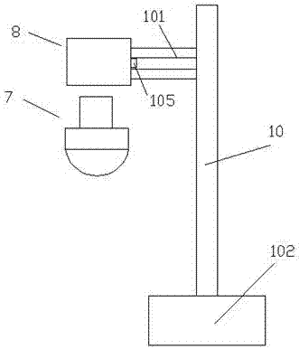
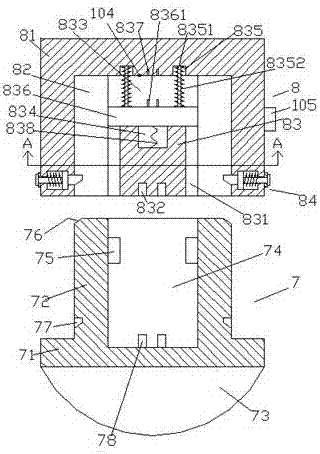
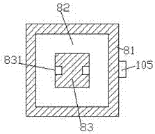
[0022] Such as Figure 1-Figure 8 As shown, an easy-to-install bridge road monitoring device of the present invention includes a base body 8 and an assembly part 7 mated with the base body 8, and the right side of the base body 8 is provided with a pillar 10, and the pillar The bottom of 10 is fixedly provided with support seat 102, and the left upper end of described pillar 10 is provided with crossbar 101, and the end of described crossbar 101 away from described pillar 10 is fixedly connected with the right side end of described seat body 8, and described seat The body 8 is composed of a casing 81, a cavity 82 and a guide block 83 arranged in the cavity 82, the top of the guide block 83 is fixedly connected with the middle end of the inner top wall of the cavity 82, and the The top of the guide block 83 is provided with a first sliding groove 833, and the two sides of the guide block 83 are provided with a second slide groove 831 extending up and down along the guide block ...


PUM


Abstract

The invention discloses a conveniently-mounted bridge road monitoring device which comprises a seat body and an assembly part connected with the seat body in a matched mode. A supporting column is arranged on the right side of the seat body; a supporting seat is fixedly arranged at the bottom of the supporting column; a transverse rod is arranged at the upper end of the left side of the supporting column; and the end, away from the supporting column, of the transverse rod is fixedly connected with the right side end of the seat body. The seat body is constituted by a sleeve shell, a cavity and a guiding-sliding block arranged in the cavity; the top of the guiding-sliding block is fixedly connected with the middle end of the top wall inside the cavity; a first slipping groove is formed in the top of the guiding-sliding block; and second slipping grooves which extend in the up-down direction along the guiding-sliding block are formed in the two sides of the guiding-sliding block. A first groove is formed in the position, at the bottom of the first slipping groove, in the guiding-sliding block; power-on holes are formed in the positions, on the top inside the first slipping groove, in the sleeve shell; and second grooves are symmetrically formed in the positions, on the two sides of the power-on holes, in the sleeve shell. Guiding-sliding rods extending downwards are arranged in the second grooves; the downward extending sections of the guiding-sliding rods penetrate into the first slipping groove and are fixedly connected with the bottom wall inside the first slipping groove; and a slipping block is connected to the guiding-sliding rods in a slipping mode. The two sides of the slipping block penetrate into the second slipping grooves and are connected with the second slipping grooves in a slipping mode; first tension springs surround the peripheries, at the upper end of the slipping block, of the guiding-sliding rods; and locking devices are symmetrically arranged in the positions, on the left side and the right side of the bottom inside the cavity, in the sleeve shell.

Description

technical field [0001] The invention relates to the technical field of bridge monitoring equipment, in particular to an easy-to-install bridge road monitoring device. Background technique [0002] At present, in order to ensure that the vehicles on the bridge road can pass normally in an orderly manner, some bridges are equipped with monitoring probes for monitoring and photographing illegal vehicles. When the existing monitoring probes are installed, the probes are generally fixed on the poles by screws and then powered by external lines. It is cumbersome, time-consuming, labor-intensive and inefficient. At the same time, since the conductive part in the probe is not equipped with any protective structure, it is very easy to touch the conductive part in the probe during maintenance and cause electric shock accidents. There is a greater safety hazard. Hidden danger. Contents of the invention [0003] The technical problem to be solved by the present invention is to provi...

Claims


Application Information

Patent Timeline
Patent Type & Authority Applications(China)
IPC IPC(8): E01F9/608E01F9/615E01F9/623
Inventor 郑浩杰
Owner 郑浩杰
Why Eureka
Try Eureka