Multifunctional large draught fan used for tunnel

A multi-functional, fan technology, applied in the ventilation of mines/tunnels, components of pumping devices for elastic fluids, mechanical equipment, etc. Work efficiency, easy to use, not easy to damage effect

Inactive Publication Date: 2017-11-03
天津中隧通风机有限公司
5 Cites 5 Cited by

AI-Extracted Technical Summary

Problems solved by technology

[0005] In order to solve the above-mentioned technical problems, the present invention provides a multifunctional large-scale fan for...

Abstract

The invention provides a multifunctional large draught fan used for a tunnel. The multifunctional large draught fan comprises a ventilation pipeline, a damp-prevention draught fan structure, a draught fan protection net, connecting flanges, a draining groove, an automatic water dispersal device, a water draining pipe and an air filter device. The damp-prevention draught fan structure is mounted on the left side and the right side of the ventilation pipeline, and the connecting flanges are mounted at the left end and the right end of the ventilation pipeline. A draught fan protection net is made of a stainless steel net, the protection effect on fan blades can be improved, and the phenomenon that impurities in the ventilation pipeline collide with the fan blades, and the fan blades are affected is avoided; a metering pump is adopted in a water pump, spraying heads can evenly spray water downwards, dust can be conveniently washed to the bottom of the ventilation pipeline, multiple water spraying heads are arranged, water can be evenly sprayed downwards, use is more convenient, and due to arrangement of an active carbon filter net, a PP cotton filter net and an HEPA filter net, flowing air in the ventilation pipeline can be purified, and during air exchange, the fan is more environment-friendly and energy-saving.

Application Domain

Pump componentsDust removal +5

Technology Topic

Active carbonEngineering +6

Image

  • Multifunctional large draught fan used for tunnel
  • Multifunctional large draught fan used for tunnel
  • Multifunctional large draught fan used for tunnel

Examples

  • Experimental program(1)

Example Embodiment

[0027] Example:
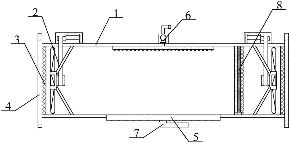
[0028] as attached figure 1 to attach Figure 4 shown
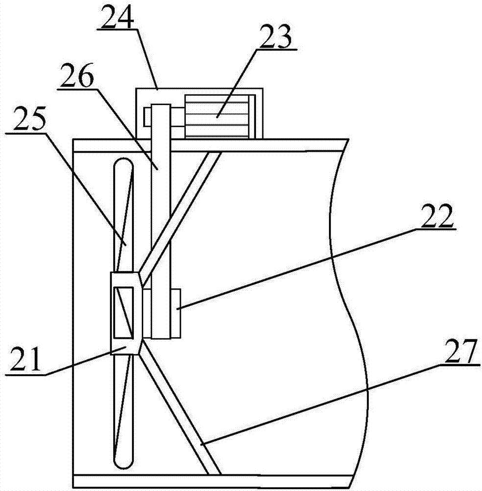
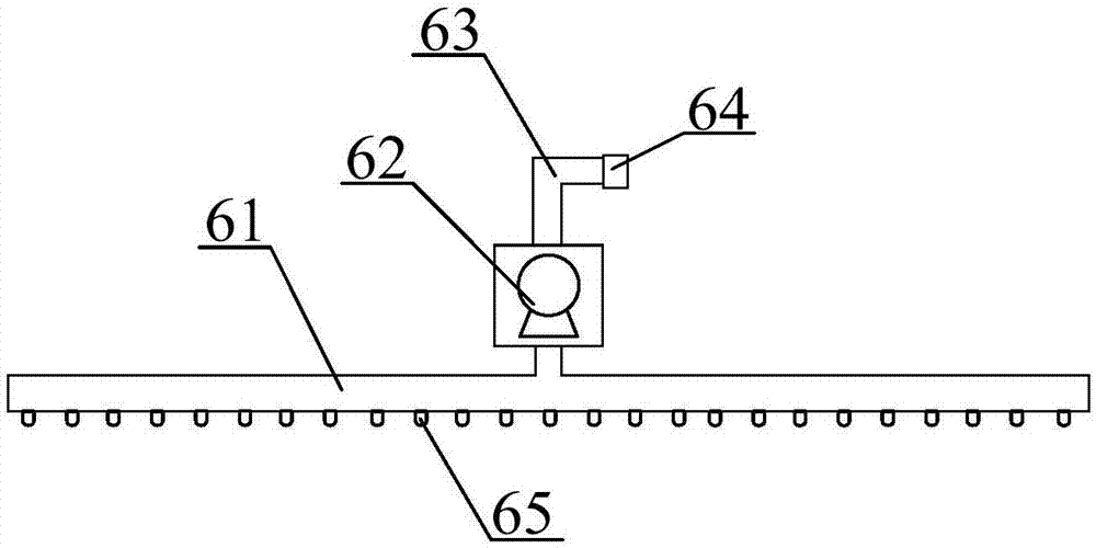
[0029] The present invention provides a multifunctional large-scale blower fan for tunnels, which includes a ventilation duct 1, a damp-proof fan structure 2, a fan protection net 3, a connecting flange 4, a drainage groove 5, an automatic water distribution device 6, a drain pipe 7 and an air blower. Filtration device 8, the described anti-moisture fan structure 2 is installed on the left and right sides of the ventilation duct 1; the described connecting flange 4 is installed on the left and right ends of the ventilation duct 1; The outside of the fan structure 2; the automatic sprinkler 6 is installed in the upper middle part of the ventilation duct 1; the drainage groove 5 is set in the lower middle part of the ventilation duct 1; The air filter device 8 is installed on the right side of the middle part of the ventilation duct 1; the damp-proof fan structure 2 includes a connecting seat 21, a driven shaft 22, a drive motor 23, a protective shell 24, fan blades 25, and a transmission belt 26 and a fixed frame 27, the connecting seat 21 is installed in the middle of the ventilation duct 1 through the fixed frame 27; the driven shaft 22 is installed on the right side of the connecting seat 21; the fan blade 25 is installed on the connecting seat 21 around the outside; the drive motor 23 is installed on the top of the ventilation duct 1, and is connected with the driven shaft 22 through the transmission belt 26; the protective shell 24 is installed on the outside of the drive motor 23.
[0030] In the above embodiment, specifically, the fan protection net 3 is made of stainless steel net.
[0031] In the above embodiment, specifically, there are multiple fixing brackets 27 .
[0032] In the above embodiment, specifically, the output shaft of the driving motor 23 is vertically corresponding to the driven shaft 22 .
[0033] In the above-mentioned embodiment, specifically, the described automatic sprinkler device 6 includes a water guide pipe 61, a water pump 62, a water inlet pipe 63, a joint 64 and a water spray head 65, and the described water guide pipe 61 is installed at the bottom of the water pump 62, and is connected with the water pump 62. The water outlet of the water pump 62 is connected; the water inlet pipe 63 is installed on the top of the water pump 62 and connected with the water inlet of the water pump 62; the joint 64 is installed on the upper end of the water inlet pipe 63; the water spray The head 65 is evenly installed on the bottom of the water guide pipe 61 .
[0034] In the above embodiment, specifically, the water pump 62 is a quantitative pump.
[0035] In the above embodiment, specifically, there are multiple water spray heads 65 .
[0036] In the above embodiment, specifically, the air filter device 8 includes an activated carbon filter screen 81, a PP cotton filter screen 82, a HEPA filter screen 83 and a water guide hole 84, the activated carbon filter screen 81, and the PP cotton filter screen 82 And HEPA filter screen 83 are installed successively from left to right; Described water guide hole 84 is offered in gac filter screen 81, the bottom of PP cotton filter screen 82 and HEPA filter screen 83.
[0037] working principle
[0038] In the working process of the present invention, when in use, the driving motor 23 rotates, and the driven shaft 22 is driven by the transmission belt 26 to make the fan blades 25 rotate to perform air exchange and exhaust. The driving motor 23 is installed on the outside of the ventilation duct 1, and passed through Protective shell 24 protection can prevent drive motor 23 from being damp and short-circuited to improve the protection effect, and then the external water is sucked into the aqueduct 61 through the water pump 62, sprayed into the ventilation duct 1 by the water spray head 65, and simultaneously the ventilation duct 1 The dust in the air washes to the bottom of the ventilation duct 1, then flows into the drain tank 5, and is discharged through the drain pipe 7, and then passes through the activated carbon filter 81, the PP cotton filter 82 and the HEPA filter 83 to drain the air in the ventilation duct 1. The flowing air is purified to prevent impurities and poisonous gas discharged in the ventilation duct 1 and improve the purification effect.

PUM

no PUM

Description & Claims & Application Information

We can also present the details of the Description, Claims and Application information to help users get a comprehensive understanding of the technical details of the patent, such as background art, summary of invention, brief description of drawings, description of embodiments, and other original content. On the other hand, users can also determine the specific scope of protection of the technology through the list of claims; as well as understand the changes in the life cycle of the technology with the presentation of the patent timeline. Login to view more.

Similar technology patents

Irregular-shaped gravity retaining wall construction process

PendingCN114059582AEnsure soil stabilityImprove the protective effect
Owner:BEIJING URBAN CONSTR GROUP

Protective gloves for paraxylene

InactiveCN105124809APrevent damage and residueImprove the protective effect
Owner:ZHEJIANG OCEAN UNIV

Classification and recommendation of technical efficacy words

  • Improve the fixed effect
  • Improve the protective effect

Oil-gas separator filter element cutting device

Owner:诺贝特空调(盐城)有限公司

Wood board cutting and scribing device for furniture production

ActiveCN113400277AImprove marking efficiencyImprove the fixed effect
Owner:徐州香梦源家具有限公司

Rotor structure of disc type motor

Owner:SHANGHAI PANGOOD POWER TECH CO LTD

Guide ail protecting cover device of end facing machine, guide rail protecting method and end facing machine

InactiveCN106735595AImprove processing efficiency and processing qualityImprove the protective effect
Owner:ZHUZHOU KAIFENG IND

Dustproof and intelligent smart home curtain

Owner:LIANYUNGANG SUNLIGHT QUARTZ CERAMICS CO LTD
Why Eureka
Try Eureka