A centrifugal clutch, a speed control system and a motorcycle

A technology for centrifugal clutches and motorcycles, applied in clutches, automatic clutches, mechanical equipment, etc., can solve the problems of reducing the sliding distance of motorcycles and prone to frustration

Active Publication Date: 2017-11-03
张小卫
View PDF10 Cites 1 Cited by
  • Summary
  • Abstract
  • Description
  • Claims
  • Application Information

AI Technical Summary

Problems solved by technology

But at this time, because the speed of the engine is lower than the speed of the clutch housing, the engine will act as a brake on the clutch, so it is easy to feel frustrated after closing the throttle; moreover, because the centrifugal shoe cannot immediately contact the cylinder of the clutch housing This will affect the inertial speed of the clutch housing, thereby reducing the sliding distance of the motorcycle after the oil is collected

Method used


Image

  • A centrifugal clutch, a speed control system and a motorcycle
  • A centrifugal clutch, a speed control system and a motorcycle
  • A centrifugal clutch, a speed control system and a motorcycle

Examples


Embodiment 1

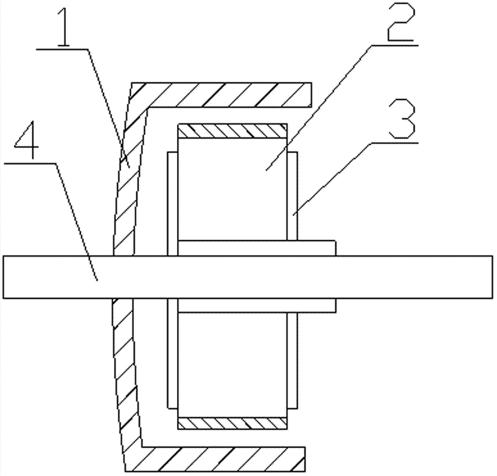
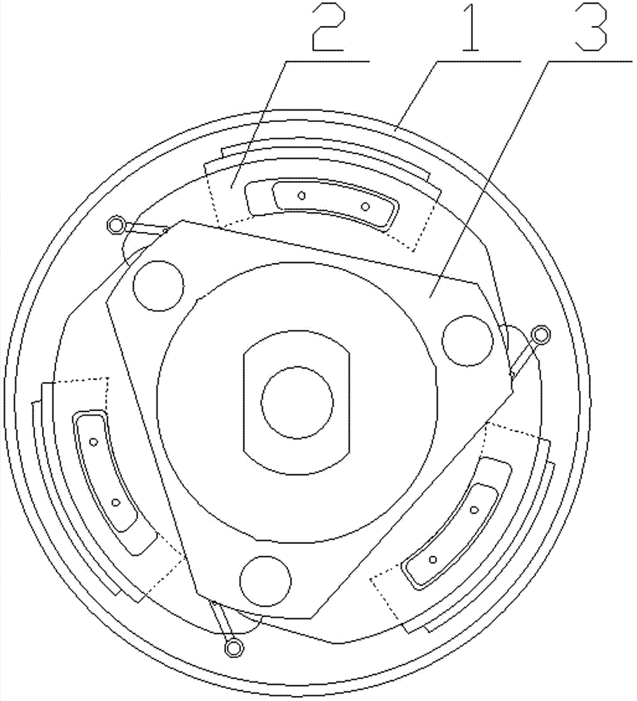
[0038] Such as figure 1 , 2 As shown, a centrifugal clutch includes a clutch housing 1 and a plurality of centrifugal shoes 2 arranged inside the clutch housing 1. The clutch housing 1 is composed of a cylindrical portion and a bottom plate covering one end of the cylindrical portion, usually approximately It is bowl-shaped, and the bottom plate of the clutch housing 1 is fixedly installed on the output shaft 4; multiple centrifugal shoes 2 are hinged on the cage 3 through pin shafts, and the adjacent centrifugal shoes 2 are connected by springs, and the cage 3 passes through The shaft sleeve is installed on the output shaft 4.

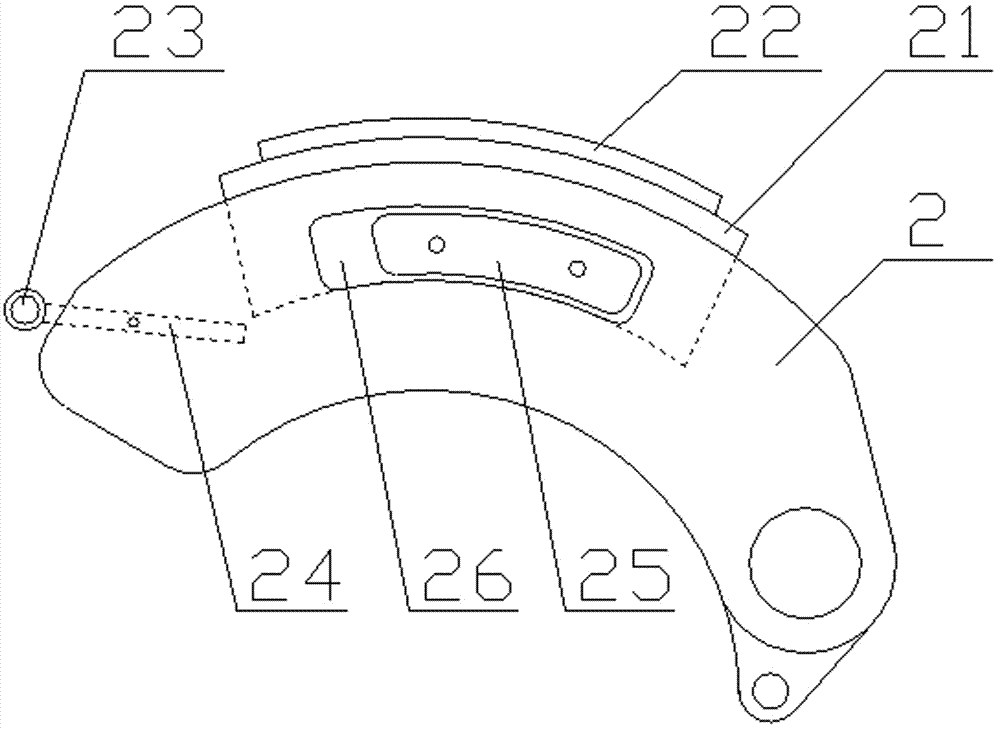
[0039] Such as image 3 , 4 As shown, the centrifugal shoe 2 has an outer arc surface and two end faces, the outer arc surface of the centrifugal shoe 2 is inlaid with a movable block 21, and the movable block 21 can move along the length of the centrifugal shoe 2. Limit movement in the direction, a return spring (not shown in the figure) is insta...

Embodiment 2

[0043] Compared with Embodiment 1, the overall structure of the clutch in this embodiment is basically the same, and the working process and principle are also the same. The main difference is that the connection structure and method between the centrifugal shoe block 2 and the movable block 21 are different. It is inlaid on the outer arc surface of the centrifugal shoe block 2, while the movable block 21 in this embodiment is sleeved on the outer arc surface of the centrifugal shoe block 2.

[0044] Such as Figures 7 to 10 As shown, in this embodiment, symmetrical arc-shaped grooves 25 are respectively provided on the two end surfaces of the centrifugal shoe block 2 or arc-shaped through holes 25 are provided through the two end surfaces. The arc-shaped grooves or arc-shaped The radian of the through hole 25 is the same as that of the outer arc surface of the centrifugal shoe block 2; Above, the lower part of the movable block 21 is provided with a limiting block 26 protrud...

Embodiment 3

[0046] Such as Figure 11 The transmission system shown includes a driving wheel assembly A, a driven wheel assembly B, a transmission belt C, and a clutch D. The clutch D is the centrifugal clutch described in Embodiment 1 or 2 of the present invention.


PUM


Abstract

The invention provides a centrifugal clutch comprising a clutch shell and a plurality of centrifugal shoe blocks arranged on the inner side of the clutch shell; each centrifugal shoe block comprises one outer circular arc surface and two end surfaces; moving blocks are embedded in or sleeve the outer circular arc surfaces of the centrifugal shoe blocks; the moving blocks can perform limited movement in the length directions of the centrifugal shoe blocks; return springs are installed between the moving blocks and the centrifugal shoe blocks; friction plates are pasted to the outer sides of the moving blocks; the end, facing the rotating direction, of each centrifugal shoe block is provided with a driving lever which is installed on the centrifugal shoe block via a hinge pin and a torsionsal spring; the upper end of each driving lever is provided with a rolling wheel or a bearing. When the moving blocks move in the rotating direction on the outer circular arc surfaces of the centrifugal shoe blocks, the moving blocks can push the driving levers to rotate around the hinge pins, so that the rolling wheels or the bearings on the driving levers protrude outward. The centrifugal shoe blocks and the clutch shell of the clutch can be separated timely after an engine is throttled down. The invention also provides a speed control system and a motorcycle employing the centrifugal clutch.

Description

technical field [0001] The invention relates to a centrifugal clutch, and also relates to a transmission system using the centrifugal clutch and a motorcycle. Background technique [0002] The centrifugal clutch transmits torque through friction. Its basic structure consists of three components: the driving part, the centrifugal body and the driven part. radial throw. When the driving part reaches the specified angular velocity, the thrown centrifuge is pressed against the inner wall of the driven part, and is forced into motion by friction force to transmit torque. The driven part of the clutch can be connected to the load directly or through mechanisms such as pulleys. [0003] In the prior art, a centrifugal clutch is also used in the speed change system of the scooter. Specifically, the speed change system of a scooter is mainly composed of two parts, the front transmission and the rear transmission; the front transmission is composed of three major parts: the driving ...

Claims


Application Information

Patent Timeline
Patent Type & Authority Applications(China)
IPC IPC(8): F16D43/18
CPCF16D43/18F16D2043/145
Inventor 张小卫
Owner 张小卫
Why Eureka
Try Eureka