Flip type vacuum wall breaking machine

A vacuum wall breaker and flip-top technology, which can be used in household appliances, applications, kitchen appliances, etc., can solve the problems of high manufacturing cost, increased transportation cost, difficult to clean, etc., and achieve the effect of wide application range.

Pending Publication Date: 2017-11-07
任安印
View PDF10 Cites 2 Cited by
  • Summary
  • Abstract
  • Description
  • Claims
  • Application Information

AI Technical Summary

Problems solved by technology

[0003] And the vacuum device of this structural form is directly used as a cup cover body. When vacuuming, it is easy to be stained with food residue or residual liquid, which is difficult to clean. Two independent lids, the tw

Method used


Image

  • Flip type vacuum wall breaking machine
  • Flip type vacuum wall breaking machine
  • Flip type vacuum wall breaking machine

Examples


no. 1 example

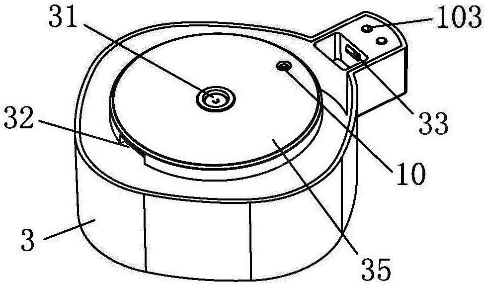
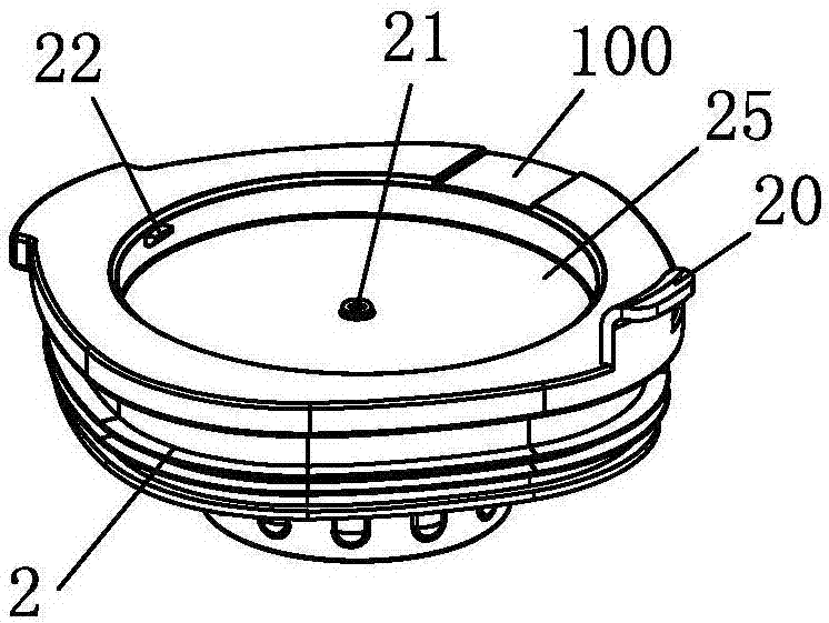
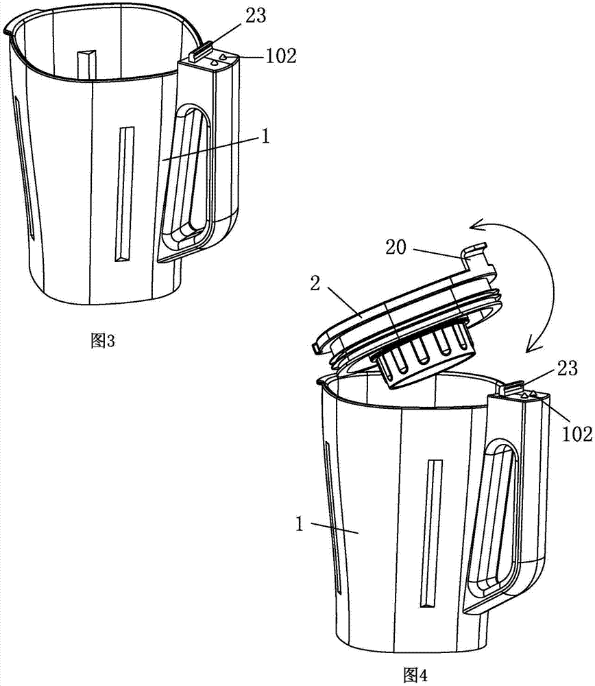
[0041] see Figure 1-Figure 6 , the clamshell vacuum breaker includes a cup body 1, a cover body 2 and a vacuum device 3, the cover body 2 is sealed and connected to the cup body 1, and the cover body 2 is provided with an air vent communicating with the cup body 1 Nozzle 21; the vacuum device 3 is detachably assembled with the cover body 2 through the flip mechanism, the flip mechanism includes a fastening part and a flip support part, and the fastening part is arranged on the vacuum device 3 and the cup body 1 close to the cup body 1 On one side of the handle, the flip support part is arranged on the side of the cover body 2 and the vacuum device 3 opposite to the handle of the cup body 1. One side of the vacuum device 3 is flipped on the cover body 2 through the flip support part, and the other side is fastened part and the cover body 2 are detachably assembled, the cover body 2 and the vacuum device 3 are independent of each other, and they can be disassembled by flipping,...

no. 2 example

[0052] see Figure 7-Figure 10 , the main difference between this clamshell vacuum breaker and the first embodiment is that the elastic lock tongue 23 elastically moves in the handle (or cover 2) of the cup body 1, and the handle (or cover body 2) of the cup body 1 The body 2) is provided with a button 101 for driving the elastic lock tongue 23 to move, and the elastic lock tongue 23 can be unlocked by pressing the button 101, so that the vacuum device 3 can be removed from the cover body 2 more easily.

[0053] Other unmentioned parts are the same as the first embodiment and will not be repeated.

no. 3 example

[0055] see Figure 11-Figure 16 The main difference between this clamshell vacuum breaker and the first embodiment is that the clamshell support part does not include the support buckle 22 (or support shaft) provided on the cover body 2, and the vacuum device 3 The buckle hole 32 (or hook) on the cover only includes the limit cavity 25 recessed on the cover body 2, and the limit platform 35 protruded on the vacuum device 3, and only one of them needs to be used for the flip support part. The technical solution can meet the operation requirements of the flip cover.

[0056] In this embodiment, the vacuum device 3 and the cover body 2 can also be separated or closed by pulling up and down, which can be understood by those skilled in the art.

[0057] The fastening part includes a lock post 24 set on the handle of the cup body 1 (or cover body 2), and a lock hole 34 set on the vacuum device 3, the two are connected by a tight fit, and naturally lock after being inserted into eac...


PUM


Abstract

The invention relates to a flip type vacuum wall breaking machine. The vacuum wall breaking machine comprises a cup body, a cover body and a vacuum-pumping device, the cup body is covered with the cover body in a sealed mode, and an air nozzle communicated with the cup body is arranged on the cover body; the vacuum-pumping device and the cover body are detachably assembled through a flip mechanism, the flip mechanism comprises a buckle part and a flip supporting part, the buckle part is arranged on the vacuum-pumping device and the side, close to a handle of the cup body, of the cup body, the flip supporting part is arranged on the cover body and the side, opposite to the handle of the cup body, of the vacuum-pumping device, one side of the vacuum-pumping device is overturned on the cover body through the flip supporting part, and the other side of the vacuum-pumping device and the cover body are detachably assembled through the buckle part. In the flip type vacuum wall breaking machine, the cover body and the vacuum-pumping device which are mutually independent are arranged at the same time, the cover body and the vacuum-pumping device can be mutually disassembled and assembled through flip-type operation, when the wall breaking machine is used conventionally, the cup body is directly covered with the cover body, the air nozzle on the cover body is used as a air hole, when the wall breaking machine is used in a vacuumized mode, the cover body is covered with the vacuum-pumping device, then the wall breaking machine can be used in the vacuumized mode, and the air nozzle is used for vacuum-pumping.

Description

technical field [0001] The invention relates to a flip-type vacuum wall breaking machine. Background technique [0002] Chinese Patent Document No. CN205612247U discloses a cooking machine, which includes a machine base, a cup body detachably mounted on the machine base, a pulverizing knife set arranged in the cup body, and a machine set arranged on the machine base and drivingly connected with the pulverizing knife set. The drive assembly; the cooking machine also includes: a cup cover, which is set independently of the cup body, and is used to open or close the cup opening of the cup body. The cup cover is provided with a sealing part and a pressure relief part. When the cup cover closes the cup mouth , the sealing part can seal the mouth of the cup; the vacuum device is arranged on the cup cover for vacuuming the inside of the cup body. The cooking machine of the present invention can maintain the pressure on the cup body, thereby preventing the ingredients in the cup bo...

Claims


Application Information

Patent Timeline
IPC IPC(8): A47J43/07
CPCA47J43/0716
Inventor 李功科任安印
Owner 任安印
Why Eureka
Try Eureka