
Convenient conveying type cutting device for natural gas pipeline production

A technology for natural gas pipelines and cutting devices, which is applied in the field of convenient transmission cutting devices for natural gas pipeline production, and can solve problems such as inability to perform continuous cutting

Active Publication Date: 2017-11-07
新昌县兴欧智能科技有限公司
View PDF9 Cites 5 Cited by
  • Summary
  • Abstract
  • Description
  • Claims
  • Application Information

AI Technical Summary

Problems solved by technology

[0006] In order to overcome the shortcomings in the prior art that natural gas pipelines mainly rely on human cutting and cannot be cut continuously, the technical problem to be solved by the present invention is to provide a natural gas pipeline that saves time and effort and can continuously cut natural gas pipelines Convenient transport cutting device for production

Method used


Image

  • Convenient conveying type cutting device for natural gas pipeline production
  • Convenient conveying type cutting device for natural gas pipeline production
  • Convenient conveying type cutting device for natural gas pipeline production

Examples


Embodiment 1

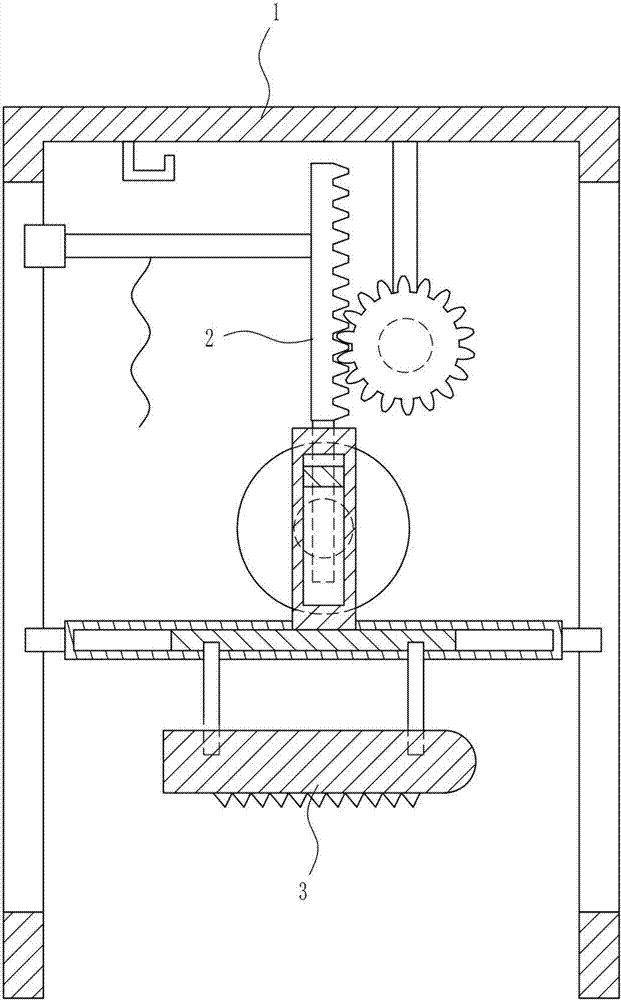
[0037] A convenient transmission cutting device for natural gas pipeline production, such as Figure 1-8 Shown, include mounting frame 1, lifting mechanism 2 and cutting mechanism 3, the top of mounting frame 1 is provided with lifting mechanism 2, the bottom of mounting frame 1 is provided with cutting mechanism 3, and cutting mechanism 3 is positioned at the lower side of lifting mechanism 2.

Embodiment 2

[0039] A convenient transmission cutting device for natural gas pipeline production, such as Figure 1-8 Shown, include mounting frame 1, lifting mechanism 2 and cutting mechanism 3, the top of mounting frame 1 is provided with lifting mechanism 2, the bottom of mounting frame 1 is provided with cutting mechanism 3, and cutting mechanism 3 is positioned at the lower side of lifting mechanism 2.

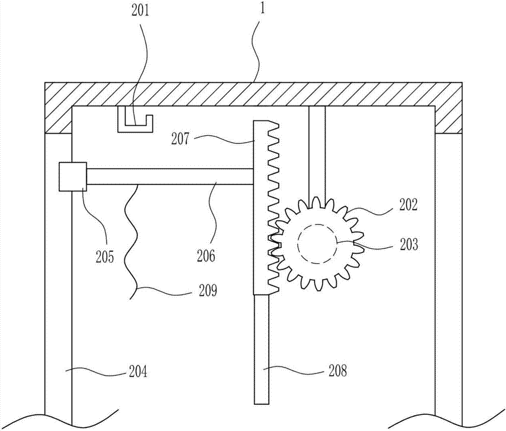
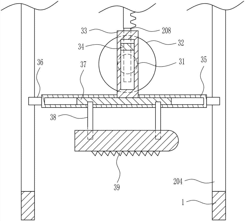
[0040] The lifting mechanism 2 includes a pole 201, a gear 202, a first motor 203, a first slide rail 204, a first slide block 205, a first connecting rod 206, a tooth bar 207, a first mounting rod 208 and a stay cord 209. The right side of the top in the frame 1 is connected with a first motor 203, the output shaft of the first motor 203 is connected with a gear 202, the left and right sides of the mounting frame 1 are symmetrically connected with a first slide rail 204, and the first slide rail on the left side 204 is slidably connected with the first slide block 205, the first slid...

Embodiment 3

[0042] A convenient transmission cutting device for natural gas pipeline production, such as Figure 1-8 Shown, include mounting frame 1, lifting mechanism 2 and cutting mechanism 3, the top of mounting frame 1 is provided with lifting mechanism 2, the bottom of mounting frame 1 is provided with cutting mechanism 3, and cutting mechanism 3 is positioned at the lower side of lifting mechanism 2.

[0043] The lifting mechanism 2 includes a pole 201, a gear 202, a first motor 203, a first slide rail 204, a first slide block 205, a first connecting rod 206, a tooth bar 207, a first mounting rod 208 and a stay cord 209. The right side of the top in the frame 1 is connected with a first motor 203, the output shaft of the first motor 203 is connected with a gear 202, the left and right sides of the mounting frame 1 are symmetrically connected with a first slide rail 204, and the first slide rail on the left side 204 is slidably connected with the first slide block 205, the first slid...


PUM


Abstract

The invention relates to a cutting device, in particular to a convenient conveying type cutting device for natural gas pipeline production. The invention aims at solving the technical problem of providing a convenient conveying type cutting device for natural gas pipeline production, wherein the convenient conveying type cutting device can save both time and labor and can be used for continuously cutting natural gas pipelines. In order to solve the above-mentioned technical problem, the convenient conveying type cutting device for natural gas pipeline production is provided and comprises an installing rack and the like, wherein a lifting mechanism is arranged on the upper portion of the installing rack, a cutting mechanism is arranged on the lower portion of the installing rack, and the cutting mechanism is located on the lower side of the lifting mechanism. According to the convenient conveying type cutting device for natural gas pipeline production, the cutting mechanism can be used for cutting the natural gas pipelines in a convenient and labor-saving manner, the lifting mechanism can drive the cutting mechanism to cut the natural gas pipelines in a convenient and labor-saving manner, an arc-shaped plate is arranged and can be used for fixing the pipelines, and therefore the pipelines can be prevented from moving in the cutting process.

Description

technical field [0001] The invention relates to a cutting device, in particular to a convenient transmission type cutting device for natural gas pipeline production. Background technique [0002] Natural gas pipelines are pipelines that transport natural gas from mining sites or processing plants to urban gas distribution centers or industrial enterprise users, also known as gas transmission pipelines. The use of natural gas pipelines to transport natural gas is the only way to transport large quantities of natural gas on land. Natural gas pipelines account for about half of the world's total pipeline length. [0003] However, the current natural gas pipelines mainly rely on manual cutting, and in the process of cutting natural gas pipelines, it is not easy to move the natural gas pipelines, so that the natural gas pipelines cannot be cut continuously. Many inconveniences. [0004] Therefore, it is urgent to develop a convenient transmission cutting device for natural gas...

Claims


Application Information

Patent Timeline
Patent Type & Authority Applications(China)
IPC IPC(8): B23D49/02B23D51/04
CPCB23D49/02B23D51/04
Inventor 文永林袁雪丁晓东
Owner 新昌县兴欧智能科技有限公司
Learn More