
Robot joint winding structure and robot

A technology of robot joints and winding structures, applied in the field of robots, can solve problems such as pulling and tearing connecting wires, and achieve the effect of improving service life and ensuring normal operation

Active Publication Date: 2017-11-07
UBTECH ROBOTICS CORP LTD
View PDF9 Cites 2 Cited by
  • Summary
  • Abstract
  • Description
  • Claims
  • Application Information

AI Technical Summary

Problems solved by technology

[0003] The invention provides a robot joint winding structure and a robot to solve the problem that the connecting wires are easily pulled and torn in the existing robot joint winding structure

Method used


Image

  • Robot joint winding structure and robot
  • Robot joint winding structure and robot
  • Robot joint winding structure and robot

Examples


Embodiment Construction

[0032] In order to have a clearer understanding of the technical features, purposes and effects of the present invention, the specific implementation manners of the present invention will now be described in detail with reference to the accompanying drawings.

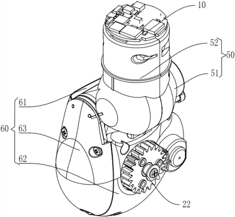
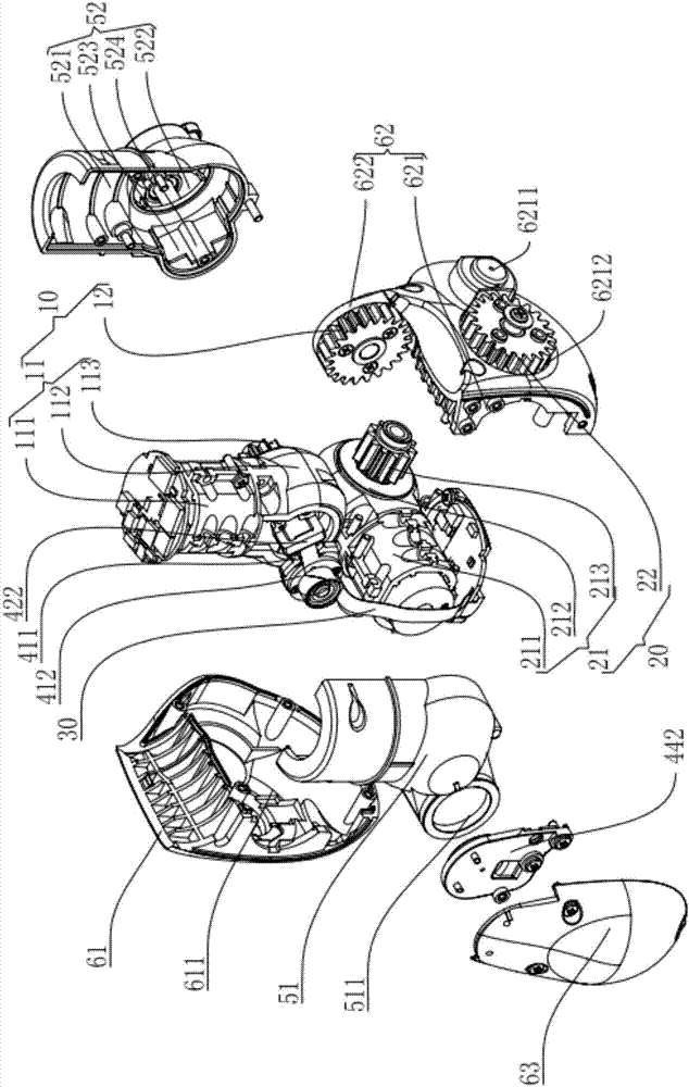
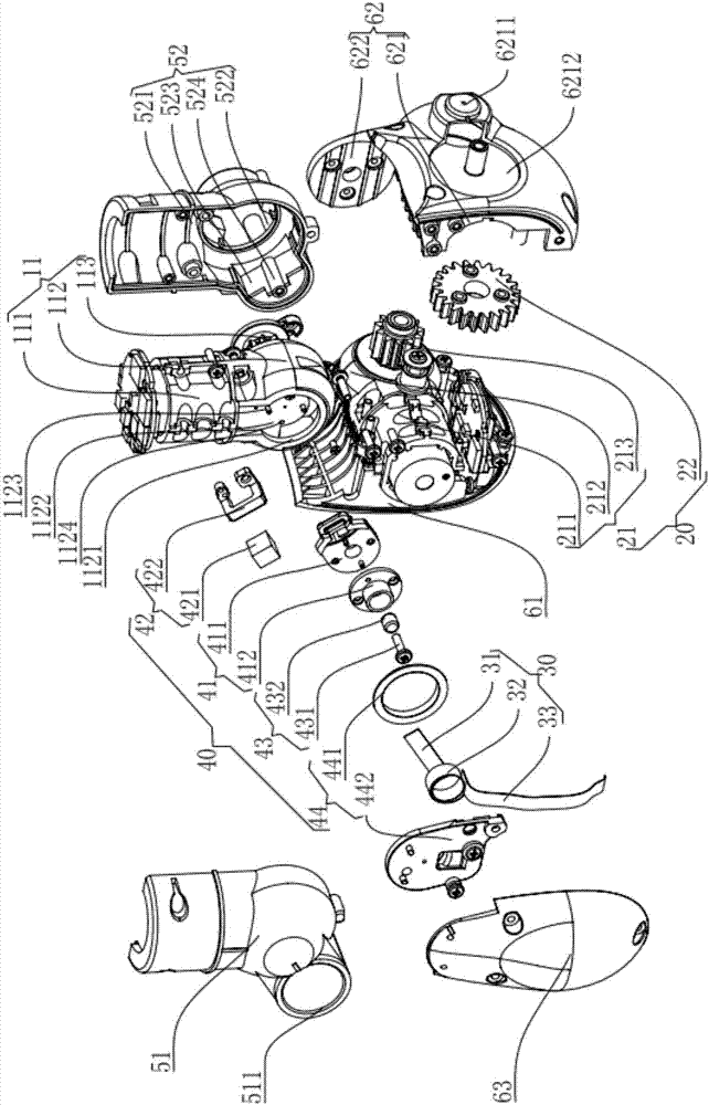
[0033] Figure 1-Figure 5 Shows the robot joint winding structure in this embodiment. Such as Figure 1-Figure 5 As shown, the robot joint winding structure includes a first servo steering gear 10, a second servo steering gear 20 that is connected to the first servo steering gear 10 and can rotate relative to the first servo steering gear 10, and is used to connect the first servo steering gear The flexible circuit board (FlexiblePrinted Circuit, FPC) 30 of the motor 10 and the second servo steering gear 20, the winding assembly 40 arranged on the first servo steering gear 10, the first shell assembled on the first servo steering gear 10 The body assembly 50 and the second housing assembly 60 assembled on the second s...


PUM


Abstract

The invention discloses a robot joint winding structure and a robot. The robot joint winding structure comprises a first servo-controller, a second servo-controller connected with the first servo-controller and capable of rotating relative to the first servo-controller, a flexible circuit board for connecting the first servo-controller with the second servo-controller and a winding assembly. The winding assembly is arranged on the first servo-controller and used for rolling up the flexible circuit board. According to the robot joint winding structure, the flexible circuit board is rolled up through the winding assembly so that the flexible circuit board can be tightened and loosened at a proper extent within the rotation angle range of the flexible circuit board, the force bearing direction of the flexible circuit board is changed, the situation that the flexible circuit board is off tracking and misplaced without the operation positioning direction, and thus the phenomena of pulling, tearing and the like occur is avoided, the service life of the flexible circuit board can be effectively prolonged, and normal work of the robot joint winding structure is ensured.

Description

technical field [0001] The invention relates to the field of robots, in particular to a robot joint winding structure and a robot. Background technique [0002] The robot is a machine device used to perform corresponding actions according to the control instructions sent by the control terminal. The robot is equipped with joint structures for building the feet, legs and elbows of the robot. The joint structure of the robot includes a steering gear. As the driving element of the joint structure of the robot, the steering gear can be connected to the controller of the robot or other steering gears to realize the electrical connection at each joint through connecting wires. During the movement of the joint structure of the existing robot, phenomena such as pulling and tearing of the flexible circuit board are likely to occur on the connecting wire, which affects the service life of the connecting wire. Contents of the invention [0003] The invention provides a robot joint w...

Claims


Application Information

Patent Timeline
Patent Type & Authority Applications(China)
IPC IPC(8): B25J17/00B25J19/00
CPCB25J17/00B25J19/00B25J19/0029B65H75/34
Inventor 熊友军胡锋陈新普舒文泉
Owner UBTECH ROBOTICS CORP LTD
Learn More