Bucket lifting mechanism and engineering vehicle using same

A lifting mechanism and bucket technology, applied in the field of mixer trucks, can solve the problems of increasing construction costs, consuming manpower and material resources, occupying space, etc., and achieve the effects of prolonging service life, reducing maintenance costs, and increasing overturning angles

Inactive Publication Date: 2017-11-07
莱州市鲁樽机械有限公司
View PDF0 Cites 0 Cited by
  • Summary
  • Abstract
  • Description
  • Claims
  • Application Information

AI Technical Summary

Problems solved by technology

[0003] Due to the single functionality of various machinery, there will be many different types of construction machinery on the construction site, which takes up a lot of space, consumes a lot of manpower and material resources, and increases the construction cost. In some small construction sites, this This problem is particularly prominent
[0004] In order to overcome the singleness of the function of the mixer truck and meet the demand for self-feeding, many mixer trucks with automatic feeding have been produced. However, during the automatic feeding process of the mixer truck, the materials need to be weighed to meet the concrete ratio. However, it is impossible to accurately determine the volume of the shoveled material during each shoveling process. In the last loading, the excess material will be stored in the bucket. In this case, the material in the bucket needs to be poured out. It is necessary to lower the loading arm first, then overturn the bucket to dump the material in the bucket, collect the bucket, lift, etc., and this situation may require multiple operations
In the case where the set loading amount needs to be reached, it will waste a lot of time to repeat such operations many times, resulting in low work efficiency, high energy consumption, and seriously affecting the energy and physical strength of personnel.
[0005] In addition, the above-mentioned automatic feeding mixer truck can only meet the needs of its own feeding, and cannot feed other vehicles or machinery, including the garbage generated during the construction process, and the transfer of materials requires special mechanical vehicles to intervene

Method used


Image

  • Bucket lifting mechanism and engineering vehicle using same
  • Bucket lifting mechanism and engineering vehicle using same
  • Bucket lifting mechanism and engineering vehicle using same

Examples


Embodiment Construction

[0030] In order to better understand the technical solutions of the present invention, the present invention will be further described below in conjunction with the accompanying drawings and specific embodiments.

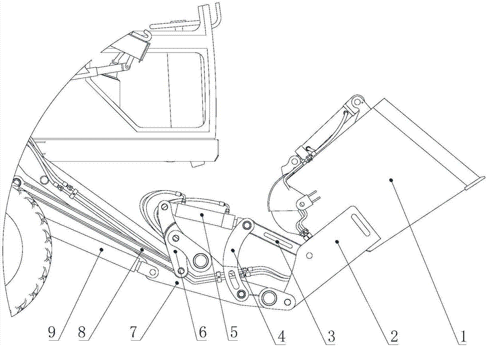
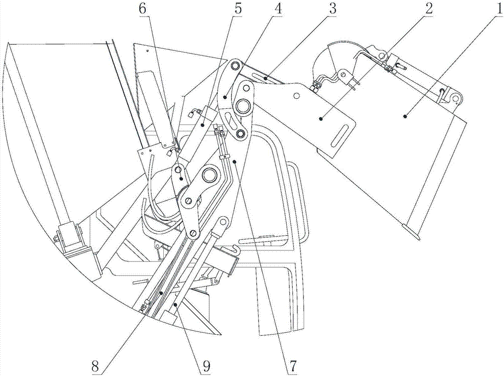
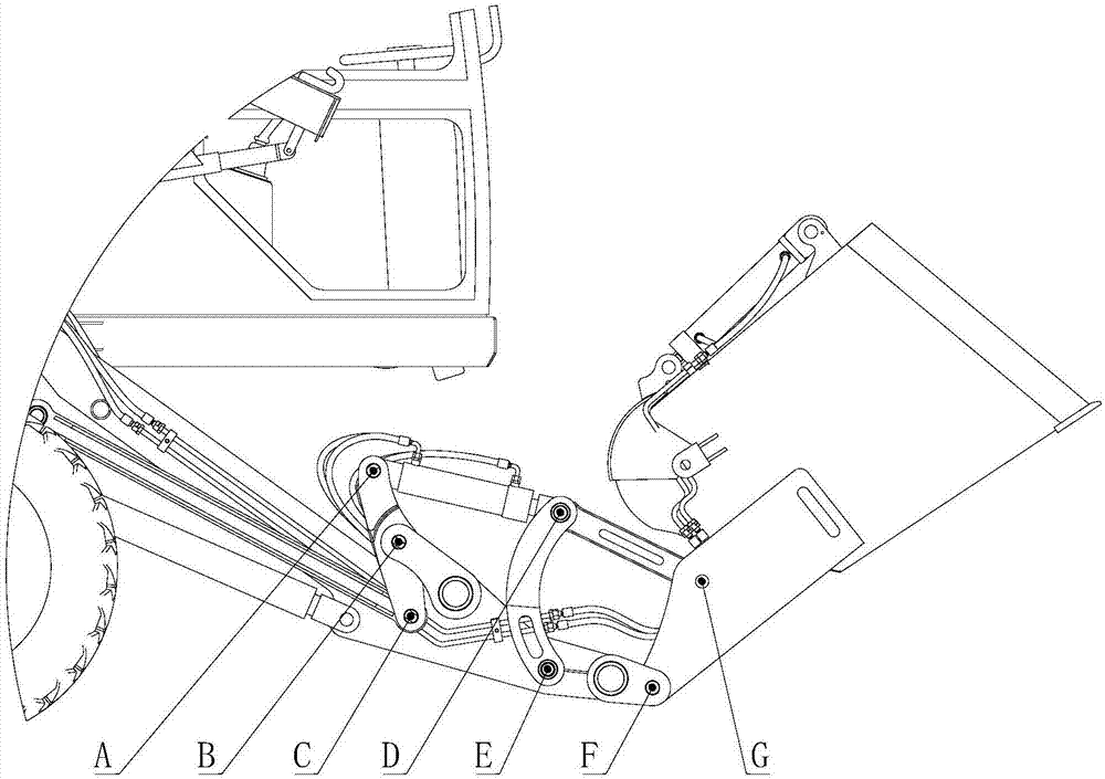
[0031] A bucket lifting mechanism, including a boom 7, a lifting power device, a pull rod 8, and a lifting and overturning device 11 for driving and tipping a bucket 1 in a lifted state, the action executing parts of the lifting power device are hinged On the boom 7, the end of the boom 7 is provided with the lifting and tilting device 11, one side of the lifting and tilting device 11 is hinged with one end of the pull rod 8, and the other side of the lifting and tilting device 11 is hinged. One side is used to connect the bucket 1, wherein the lifting power device is set on the second type of general chassis provided by the manufacturer, which will not be repeated here. The use of this lifting and tilting device 11 can make the bucket 1 in the lifting state. Comple...


PUM


Abstract

The invention discloses a bucket lifting mechanism and an engineering vehicle using the mechanism. The action execution part of the power device is hinged on the boom, the end of the boom is provided with the lifting and tilting device, one side of the lifting and tilting device is hinged with one end of the pull rod, and the lifting and tilting device The other side is used to connect the bucket. Using this lifting and tilting device can make the bucket complete the unloading action in the lifted state, avoiding the need to pour out the material in the bucket when the traditional self-loading mixer truck needs to first Putting down the boom, overturning the bucket to dump the material, and then retracting and lifting the bucket is complicated and time-consuming. An engineering vehicle uses the above-mentioned bucket lifting mechanism to load, unload, transfer, and accumulate other materials and garbage, and realize "one machine with multiple functions".

Description

technical field [0001] The invention relates to the technical field of mixer trucks, in particular to a bucket lifting mechanism and an engineering vehicle using the mechanism. Background technique [0002] Mixer truck, a special truck used to transport concrete for construction, consists of a car chassis and a special device for mixing and transporting concrete. The chassis of the concrete mixer truck produced in my country mostly adopts the second-class general-purpose chassis provided by the vehicle manufacturer. Its special mechanism mainly includes power take-off, front and rear brackets of mixing drum, reducer, hydraulic system, mixing drum, operating mechanism, cleaning system, etc. The working principle is that the power of the car chassis is taken out through the power take-off device, and the variable pump of the hydraulic system is driven to convert the mechanical energy into hydraulic energy and transmit it to the quantitative motor. Mixing, this type of truck ...

Claims


Application Information

Patent Timeline
Patent Type & Authority Applications(China)
IPC IPC(8): B28C5/42
CPCB28C5/4241
Inventor 阎军吉阎相宇
Owner 莱州市鲁樽机械有限公司
Why Eureka
Try Eureka