
Drying equipment

A technology of drying equipment and drying area, applied in drying, drying machine, lighting and heating equipment and other directions, can solve the problems of high cost, complex installation structure, screw wear, etc., to increase the contact area and improve the drying rate. The effect of drying efficiency

Active Publication Date: 2017-11-07
JIANGSU XCMG CONSTR MASCH RES INST LTD
View PDF6 Cites 12 Cited by
  • Summary
  • Abstract
  • Description
  • Claims
  • Application Information

AI Technical Summary

Problems solved by technology

However, the design and installation structure of this lifting blade is complicated, and the cost is high, and when the production material changes frequently, dozens or hundreds of blades need to be frequently adjusted to adapt to different working conditions, and the labor intensity is relatively high; After a period of time, the bolts and screws are prone to wear and become invalid, and no longer have the adjustment function, and the effect of adjusting the density of the material curtain cannot be realized
[0008] In view of the problem that the distance of the material curtain affects the fuel combustion efficiency, the technical solution commonly used in the prior art is to increase the length of the combustion zone to ensure that the flame can fully burn
However, although increasing the length of the combustion zone can ensure the space required for fuel combustion, it will lead to an increase in the overall length of the drying cylinder, and the work energy consumption and production costs will also increase.

Method used


Image

  • Drying equipment
  • Drying equipment
  • Drying equipment

Examples


Embodiment Construction

[0063] The technical solutions in the embodiments will be clearly and completely described below in conjunction with the drawings in the embodiments of the present invention. Obviously, the described embodiments are only a part of the embodiments of the present invention, rather than all the embodiments. Based on the embodiments of the present invention, all other embodiments obtained by those of ordinary skill in the art without creative work fall within the protection scope of the present invention.

[0064] In the description of the present invention, it should be understood that the terms "center", "transverse", "longitudinal", "front", "rear", "left", "right", "upper", "lower", " The orientation or positional relationship indicated by "vertical", "horizontal", "top", "bottom", "inner", "outer" etc. is based on the orientation or positional relationship shown in the drawings, and is only for the convenience of describing the present invention and The description is simplifie...


PUM


Abstract

The invention relates to drying equipment. The drying equipment comprises a burning area (1) and a drying area (2). A roller (6) is arranged in the drying area (2). The inner wall surface of the roller (6) is provided with material lifting blades which are used for lifting up materials conveyed into the roller (6) from the bottom of the roller (6) and enabling the materials to fall off to form a material curtain along with rotation of the roller (6), so that the materials conduct heat exchange with hot gas generated in the burning area (1) in the falling process of the materials. According to the drying equipment provided by the embodiment of the invention, the inner wall surface of the roller is provided with the material lifting blades; the materials can be lifted up from the bottom of the roller and conveyed into the roller through the material lifting blades and can be made to fall off to form the material curtain along with rotation of the roller, so that the materials conduct heat exchange with the hot gas generated in the burning area in the falling process, and then the drying effect of the materials is achieved. The materials are lifted up and fall off through the material lifting blades. The contact area of the materials with the hot gas is increased. The drying efficiency of the materials is improved.

Description

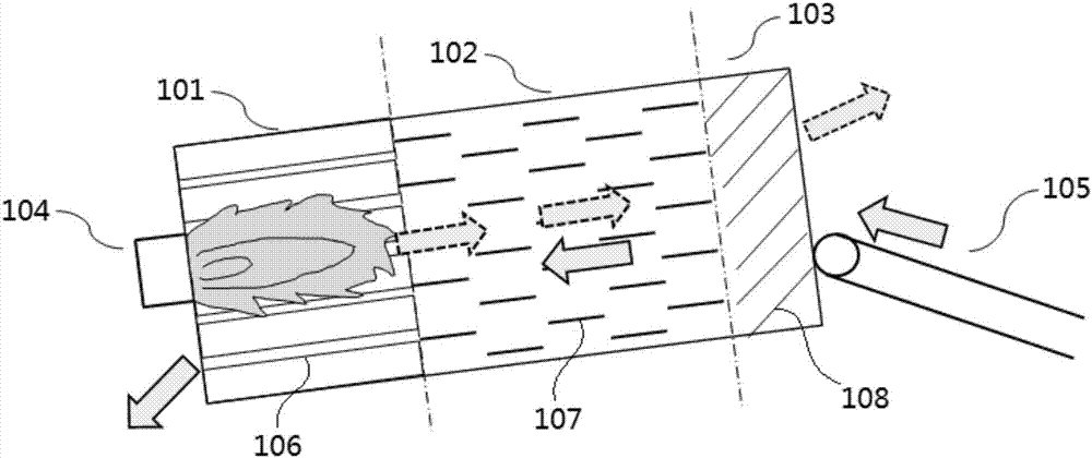
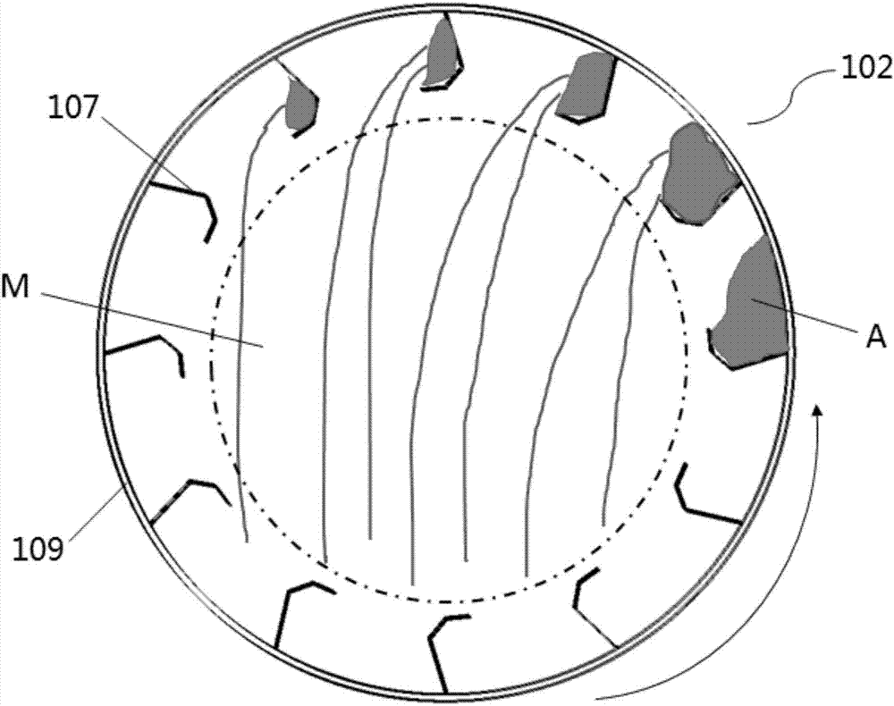
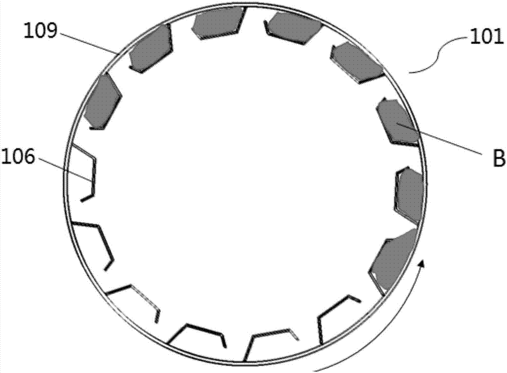
Technical field [0001] The invention relates to the technical field of material drying, in particular to a drying equipment. Background technique [0002] The drying cylinder is the core component of the traditional drying equipment. It uses the convection heat exchange process between the material and the hot flue gas in the drum to achieve the drying and heating of the material. It is widely used in building materials, metallurgy, ore and other fields. Such as figure 1 As shown, the drying cylinder in the prior art is generally divided into three parts: the combustion zone 101, the drying zone 102 and the material guide zone 103. After the material enters the drying cylinder by the conveying device 105, it passes through the material guide zone 103. The function of the spiral blade 108 quickly enters the drying zone 102. Such as figure 2 As shown, the material forms a pile A under the action of the lifting blades 107 uniformly distributed on the inner wall of the drum 109, an...

Claims


Application Information

Patent Timeline
Patent Type & Authority Applications(China)
IPC IPC(8): F26B11/06F26B25/04F26B25/16
CPCF26B11/0486F26B25/04F26B25/16
Inventor 吕龙飞王晨刘晓东杨伦磊
Owner JIANGSU XCMG CONSTR MASCH RES INST LTD
Learn More