
Turbine rotor balance test clamp and balance test device

A turbine rotor and balance test technology, which is applied in the static/dynamic balance test, measuring device, machine/structural component test, etc., can solve the problem that the turbine rotor cannot obtain real and accurate balance data, etc.

Active Publication Date: 2017-11-07
CHINA HANGFA SOUTH IND CO LTD
View PDF7 Cites 9 Cited by
  • Summary
  • Abstract
  • Description
  • Claims
  • Application Information

AI Technical Summary

Problems solved by technology

[0005] The invention provides a turbine rotor balance test fixture and a balance test device to solve the technical problem that the turbine rotor cannot obtain true and accurate balance data during the balance test

Method used


Image

  • Turbine rotor balance test clamp and balance test device
  • Turbine rotor balance test clamp and balance test device
  • Turbine rotor balance test clamp and balance test device

Examples


Embodiment Construction

[0030] It should be noted that, in the case of no conflict, the embodiments in the present application and the features in the embodiments can be combined with each other. The present invention will be described in detail below with reference to the accompanying drawings and examples.

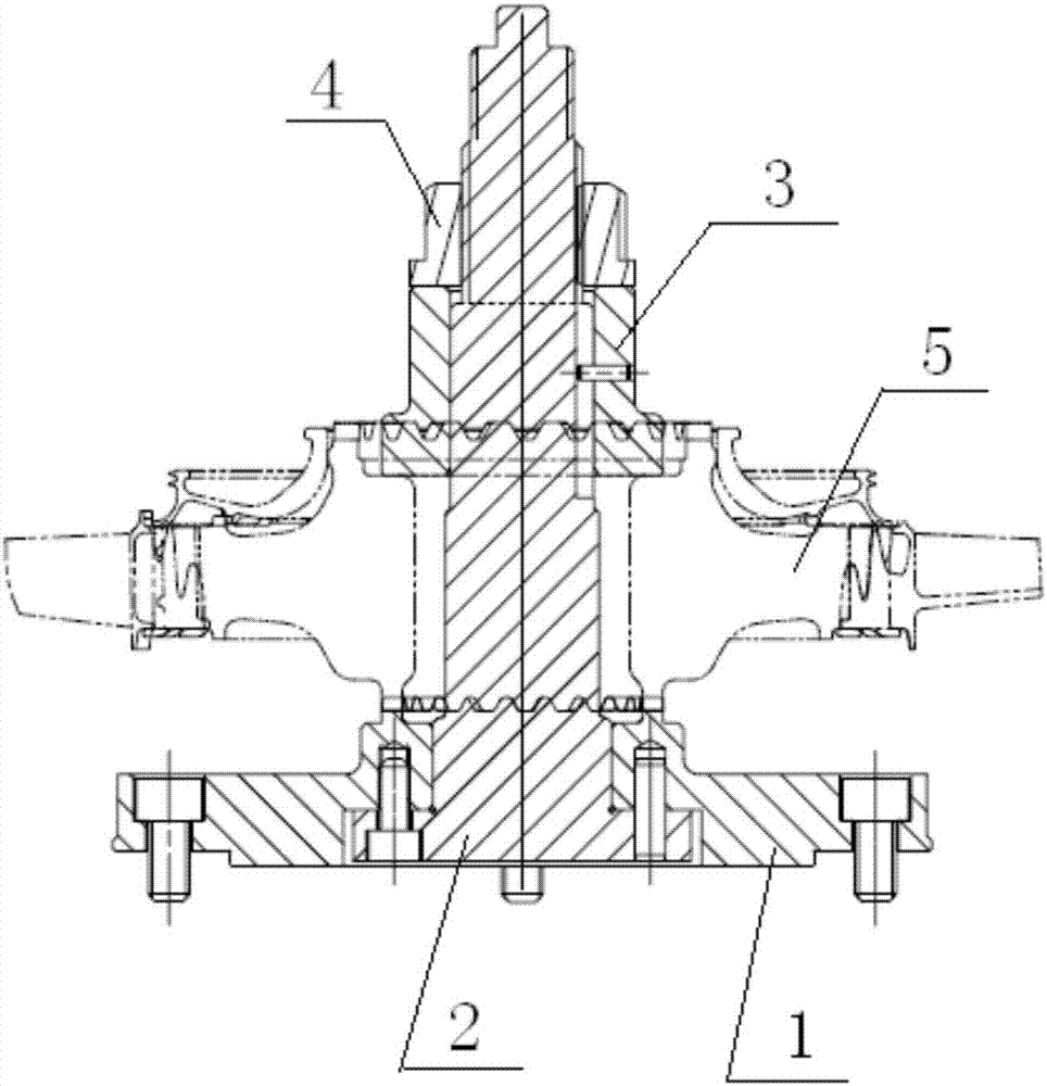
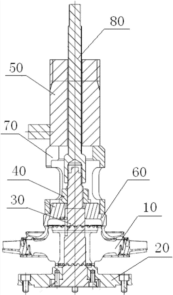
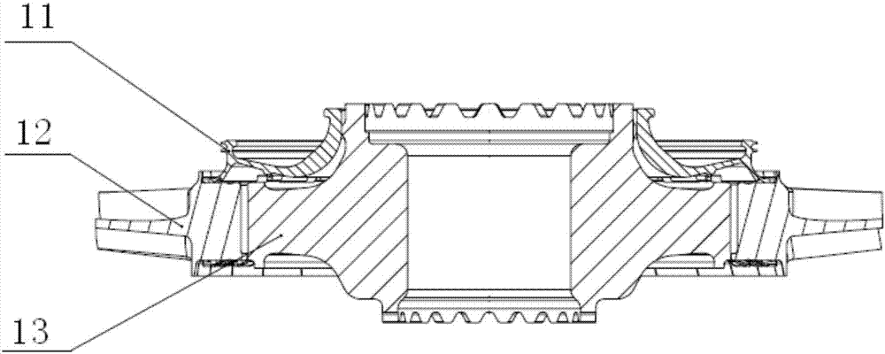
[0031] refer to figure 2 , the preferred embodiment of the present invention provides a turbine rotor balance test jig, which is used for clamping the turbine rotor assembly 10 on a balancing machine to perform a balance test. The balance test jig includes: a base 20 for fixing the turbine rotor assembly 10 and installed on a balancing machine, a positioning rod 30 for tensioning and centering the turbine rotor assembly 10 passing through the turbine rotor assembly 10 and affixed to the base 20 , a force applying device 50 for applying pressure to the turbine rotor assembly 10 , and a locking device 40 sleeved on the positioning rod 30 for maintaining a preset pressure value when the force ap...


PUM


Abstract

The invention discloses a turbine rotor balance test clamp and a balance test device. The turbine rotor balance test clamp is used for clamping a turbine rotor assembly on a balance machine for a balance test, and a force application device exerts pressure on the turbine rotor assembly to enable the turbine rotor assembly to reach preset pressure in the working state of an engine; the pressure is kept stable and not reduced by means of a locking device, and then the force application device is removed; the balance machine is used for carrying out the balance test on a turbine rotor. According to the turbine rotor balance test clamp and the balance test device, the actual stress condition of the turbine rotor during operation of the engine is simulated so that balance data of the turbine rotor can be accurately measured through the balance machine, and the technical problems that a balance test clamp in the prior art cannot obtain true and accurate balance data is solved.

Description

technical field [0001] The invention relates to the field of aero-engine assembly, in particular to a turbine rotor balance test fixture and a balance test device. Background technique [0002] Aeroengine power or gas turbine rotor assembly (rotor with blades) must be balanced before being assembled into the engine to simulate the state of the rotor assembly when the engine is working, and check the balance of the high-speed rotation of the rotor assembly. Generally, the unbalance of the rotor is required to be less than 5g / mm. The turbine rotor rotates under force when the engine is working, so when doing a balance test on the turbine rotor, a certain pressure should also be applied to the turbine rotor, and the balance test should be done at the same time. The current balance test is only for the balance test of the turbine rotor assembly, without really simulating the balance test of the turbine rotor assembly under the working condition of the engine, which may not obt...

Claims


Application Information

Patent Timeline
IPC IPC(8): G01M1/02
CPCG01M1/02
Inventor 高晓龙庞文婷黄超熊炳文张菊绒
Owner CHINA HANGFA SOUTH IND CO LTD
Learn More