Control of crystal orientation and stress in sputter deposited thin films

a technology of sputtering equipment and crystal orientation, applied in the direction of crystal growth process, polycrystalline material growth, vacuum evaporation coating, etc., can solve the problems of increasing the level of control of film properties, filling voids and atomic level vacancies, and formation of crystalline defects such as interstitial atoms, and achieves effective control and promote stress control

Inactive Publication Date: 2009-10-01
OEM GROUP INC
View PDF70 Cites 43 Cited by
  • Summary
  • Abstract
  • Description
  • Claims
  • Application Information

AI Technical Summary

Problems solved by technology

These films are being utilized in increasingly demanding ways that require increasing levels of control of the film properties.
Ion bombardment during deposition results in argon entrapment and atomic peening, which promotes the displacement of surface atoms towards deeper positions in the bulk of the growing films leading to the filling of voids and atomic level vacancies and the formation of crystalline defects such as interstitial atoms.
It is necessary to point out that implementing aluminum nitride film stress control by manipulating the magnetic field influences the erosion profile of the sputtering target and, also, that it is a technically inconvenient method for industrial sputtering equipment.
Adjustment of the pressure is also inconvenient since pressure can greatly affect other important characteristics of the sputter deposited films.
Deposition on metal underlayers, however, is often challenging because the crystal orientation of the deposited aluminum nitride films depends on the crystallographic orientation of the underlayers, on the surface roughness, surface cleanliness, among other properties of the bottom electrode upon which the aluminum nitride is deposited.

Method used


Image

  • Control of crystal orientation and stress in sputter deposited thin films
  • Control of crystal orientation and stress in sputter deposited thin films
  • Control of crystal orientation and stress in sputter deposited thin films

Examples


Embodiment Construction

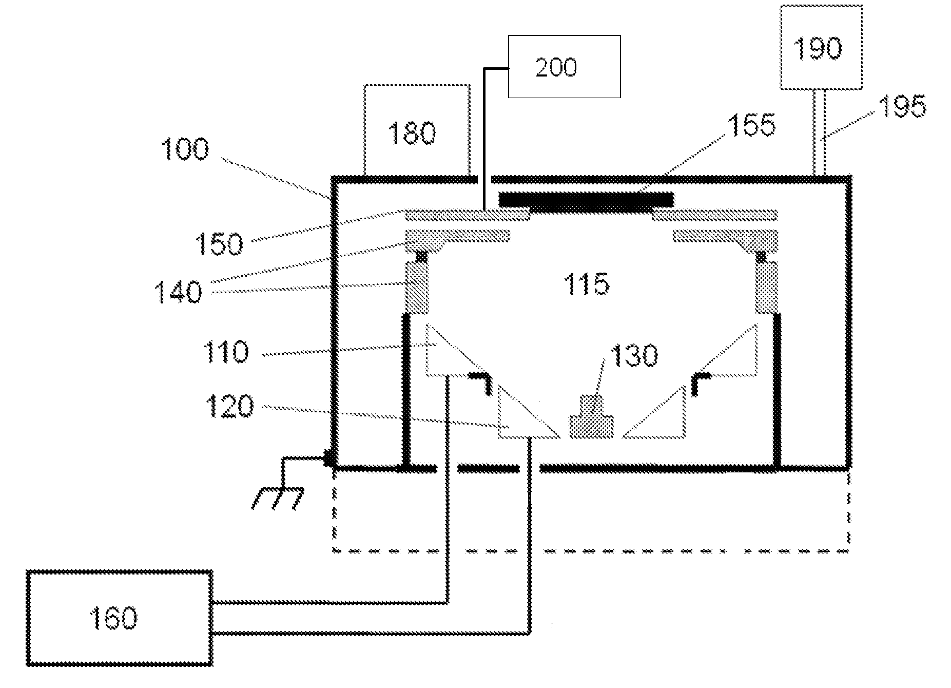
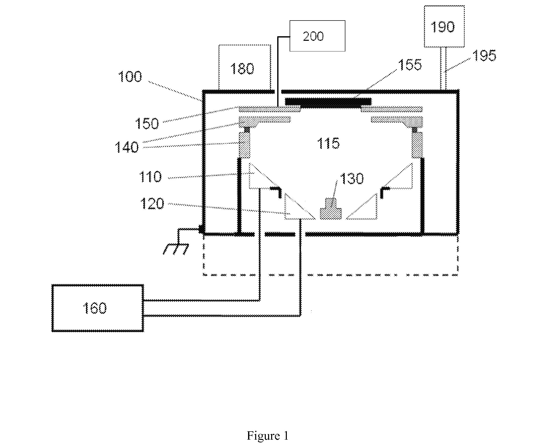
[0039]In one embodiment of the present invention, preferred crystal orientation and effective stress control are achieved simultaneously in piezoelectric aluminum nitride films deposited with ac (for example, 40 kHz) reactive sputtering processes using a dual cathode S-Gun magnetron, and also in molybdenum electrodes deposited by a dc powered version of the S-Gun. In this preferred embodiment, the sputter system employed is the Endeavor-AT manufactured by Tegal Corporation equipped with the S-Gun magnetrons, but the result of this invention can be applied to other deposited films and other sputter systems.

[0040]In the schematic illustration provided in FIG. 1, a number of key attributes of the preferred embodiment are shown. The preferred embodiment consists of a process chamber 110 within which is contained a cavity 115. Two conical sputter targets, an outer sputter target 110 and an inner sputter target 120, are mounted concentrically around a center shield 130. Center shield 130 ...


PUM

PropertyMeasurementUnit
bias poweraaaaaaaaaa
thicknessaaaaaaaaaa

Abstract

A two step thin film deposition process is disclosed to provide for the simultaneous achievement of controlled stress and the achievement of preferred crystalline orientation in sputter-deposited thin films. In a preferred embodiment, a first relatively short deposition step is performed without substrate bias to establish the crystalline orientation of the deposited film followed by a second, typically relatively longer deposition step with an applied rf bias to provide for low or no stress conditions in the growing film. Sputter deposition without substrate bias has been found to provide good crystal orientation and can be influenced through the crystalline orientation of the underlying layers and through the introduction of intentionally oriented seed layers to promote preferred crystalline orientation. Conversely, sputter deposition with substrate bias has been found to provide a means for producing stress control in growing films.

Description

[0001]This application claims priority from U.S. provisional patent application Ser. No. 61 / 039,354, filed on Mar. 25, 2008, entitled “Stress control in reactive sputtering”, which is incorporated herein by reference.FIELD OF THE INVENTION[0002]The present invention relates to a method for the deposition of thin films that simultaneously exhibit preferred crystalline orientation and preferred stress characteristics in sputter deposition equipment.BACKGROUND OF THE INVENTION[0003]In recent years, remarkable progress has been achieved in developing new techniques for sputter deposition of oxide, nitride, and oxy-nitride thin films such as aluminum nitride, aluminum oxide, silicon nitride, silicon oxide, tantalum oxide, and tantalum oxynitride, among others. These films are being utilized in increasingly demanding ways that require increasing levels of control of the film properties. For example, piezoelectric aluminum nitride films used in various electroacoustic applications such as ...

Claims


Application Information

Patent Timeline
Patent Type & Authority Applications(United States)
IPC IPC(8): B05D3/14C23C14/34B05D5/00
CPCC23C14/024C23C14/025C23C14/0617C30B29/403C23C14/54C30B23/02C23C14/14C30B23/002H10N30/076
Inventor FELMETSGER, VALERYLAPTEV, PAVEL N.
Owner OEM GROUP INC
Why Eureka
Try Eureka