Eureka AIR delivers breakthrough ideas for toughest innovation challenges, trusted by R&D personnel around the world.

Metal material detection clamp

A technology for detecting jigs and metal materials, which is applied in analytical materials, measuring devices, preparation of samples for testing, etc., can solve problems such as burden, complex shape, and complex structure, and achieve extended service life, increased friction, and improved safety. Effect

Inactive Publication Date: 2017-11-07
CENXI DONGZHENG POWER TECH DEV
View PDF0 Cites 3 Cited by
  • Summary
  • Abstract
  • Description
  • Claims
  • Application Information

AI Technical Summary

Problems solved by technology

[0002] With the advancement of the national standardization system, the standards of all walks of life are also increasing, and the requirements for various indicators are constantly improving. The downstream customers' control indicators for products are increasingly relying on measurable quantitative data as the basis for judgment. During the testing process, The metal material to be inspected must not be displaced, and the sample to be inspected is generally fixed by a hand-held method or by using the structure of the sample itself. However, in the actual application process, due to the complex structure and shape of the metal material, it is impossible to rely on its own structure to keep it fixed, and the hand-held method cannot guarantee the stability of the sample. Under such circumstances, fixtures should be born in time. However, the existing metal material fixtures have simple functions, not only poor fixation, but also for some leveling needs. Metal components are powerless. In addition, the existing fixtures are often fixed by manpower. Due to the limited strength of human beings, there are often problems such as insufficient fixation. These will greatly affect the detection of metal materials and give the detection process bring a great burden

Method used

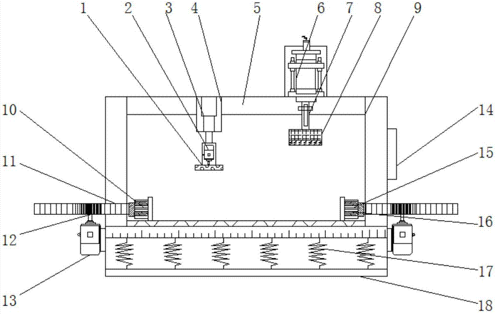

Image

  • Metal material detection clamp
  • Metal material detection clamp
  • Metal material detection clamp

Examples


Embodiment Construction

[0014] The following will clearly and completely describe the technical solutions in the embodiments of the present invention with reference to the accompanying drawings in the embodiments of the present invention. Obviously, the described embodiments are only some, not all, embodiments of the present invention. Based on the embodiments of the present invention, all other embodiments obtained by persons of ordinary skill in the art without making creative efforts belong to the protection scope of the present invention.

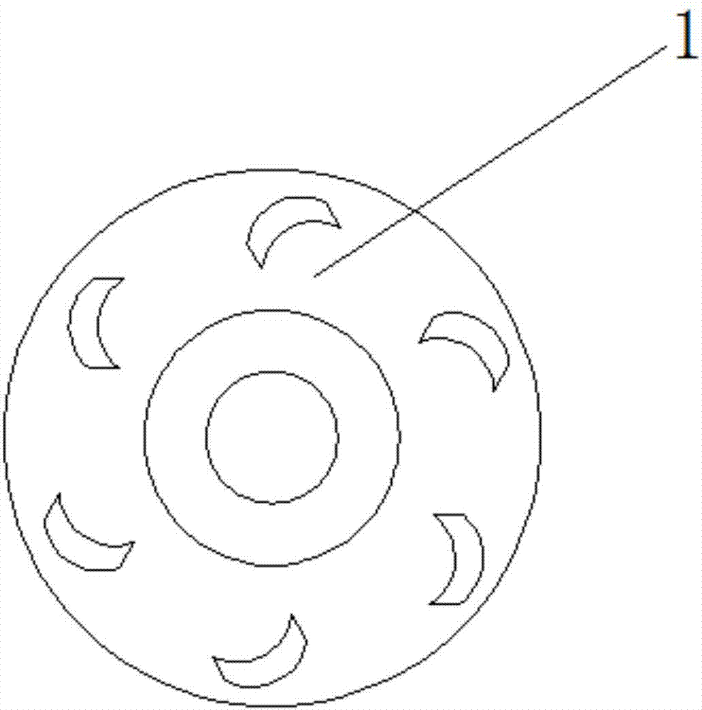
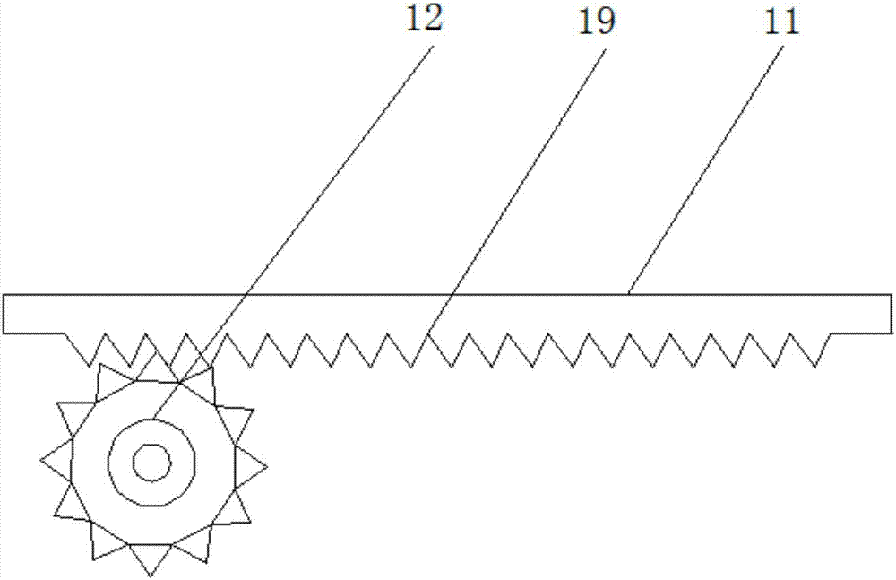
[0015] see Figure 1-3 , an embodiment provided by the present invention: a metal material detection fixture, including a leveling tool 1, a cross bar 5, a cylinder 6 and a base 18, both sides of the top of the base 18 are equipped with support rods 9, and the inside of the base 18 The bottom end of the base 18 is provided with a shock-absorbing layer 17, and one side of the base 18 is engraved with a scale line, so that the device has a metering function. The...


PUM


Abstract

The invention discloses a metal material detection clamp. The clamp comprises a leveling cutting tool, a cross bar, a cylinder and a base. Both sides of the top end of the base are provided with supporting rods, the bottom end inside the base is provided with a damping layer, the cross bar is arranged between tops of the supporting rods, one end of the top of the cross bar is provided with a shell, the top in the shell is provided with a hydraulic telescopic rod, the bottom end of the hydraulic telescopic rod is provided with a first motor, the bottom end of the first motor is provided with the leveling cutting tool, the other end of the top of the cross bar is provided with the cylinder and the bottom end of the cylinder is provided with a telescopic rod. Through scale lines, the whole device has a metering function. Through use of the damping layer, a gravity test on a metal material proves that the clamp can be protected and a service life of the clamp is prolonged.

Description

technical field [0001] The invention relates to the technical field of detection fixtures, in particular to a metal material detection fixture. Background technique [0002] With the advancement of the national standardization system, the standards of all walks of life are also increasing, and the requirements for various indicators are constantly improving. The downstream customers' control indicators for products are increasingly relying on measurable quantitative data as the basis for judgment. During the testing process, The metal material to be inspected must not be displaced, and the sample to be inspected is generally fixed by a hand-held method or by using the structure of the sample itself. However, in the actual application process, due to the complex structure and shape of the metal material, it is impossible to rely on its own structure to keep it fixed, and the hand-held method cannot guarantee the stability of the sample. Under such circumstances, fixtures shou...

Claims


Application Information

Patent Timeline
IPC IPC(8): G01N3/04G01N1/28B21D1/00B21D3/00
CPCB21D1/00B21D3/00G01N1/286G01N3/04G01N2203/0411
Inventor 关松生
Owner CENXI DONGZHENG POWER TECH DEV
Why Eureka
Eureka Blog
Learn More