Eureka AIR delivers breakthrough ideas for toughest innovation challenges, trusted by R&D personnel around the world.

A multi-channel can bus data recording storage device

A CAN bus and storage device technology, which is applied in the field of multi-channel CAN bus data recording and storage devices, can solve the problems of less CAN bus channels, slow transmission speed, and poor reliability, and achieve fast storage speed, speed improvement, and high reliability. Effect

Active Publication Date: 2020-11-17
BEIJING INST OF SPACE LAUNCH TECH +1
View PDF7 Cites 0 Cited by
  • Summary
  • Abstract
  • Description
  • Claims
  • Application Information

AI Technical Summary

Problems solved by technology

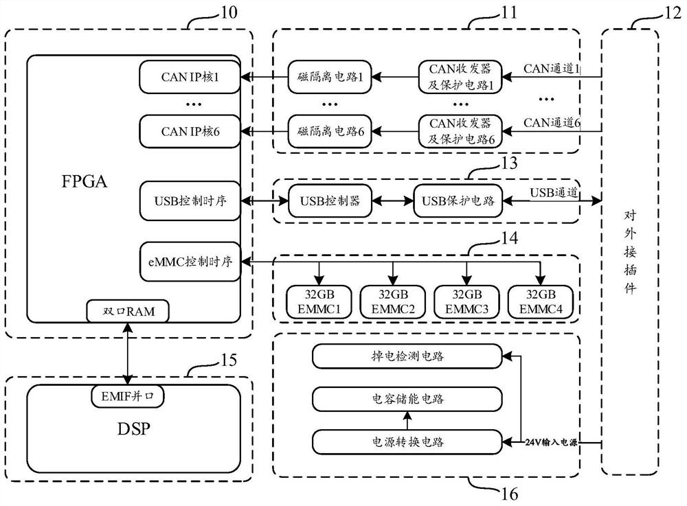
[0005] In order to solve the problems of the existing CAN bus data storage devices, such as slow transmission speed, poor reliability, and easy damage in unexpected situations such as power failure, the present invention innovatively develops a multi-channel CAN bus data recording and storage device, based on DSP+FPGA Architecture, combined with multi-channel bus transceiver circuit and power supply circuit, thus realizing the high-speed storage of multi-channel CAN bus data, and improving the power-off reliability and service life of the storage device
[0007] Based on the frame structure of DSP+FPGA, the present invention can record multi-channel CAN bus data at the same time, and solve the problems such as few CAN bus channels, slow transmission speed and poor reliability of traditional CAN bus data recording and storage devices; The power-down detection circuit that monitors whether the power signal is power-down and the capacitive energy storage circuit used to provide data buffer power support after power-down, so as to solve the problem that the traditional CAN bus data recording storage device is easily damaged in unexpected situations such as power-off, Improve the reliability of the present invention

Method used


Image

  • A multi-channel can bus data recording storage device
  • A multi-channel can bus data recording storage device

Examples


Embodiment Construction

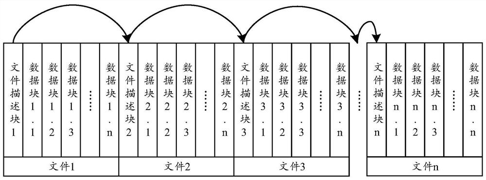
[0028] The multi-channel CAN bus data recording and storage device of the present invention will be explained and illustrated in detail below in conjunction with the accompanying drawings.

[0029] like figure 1 and 2 As shown, the invention discloses a multi-channel CAN bus data record storage device. This multi-channel CAN bus data record storage device comprises FPGA controller 10, DSP controller 15, multi-channel bus transceiver circuit 11, external connector 12, data storage circuit 14 and power supply circuit 16; FPGA controller 10 and DSP controller 15 connection, the FPGA controller 10 is also respectively connected with the multi-channel bus transceiver circuit 11, the data storage circuit 14 and other circuits, the present invention innovatively adopts the core controller architecture combined with DSP+FPGA, and expands the components with corresponding functions through the periphery of the core controller , that is, the peripheral circuit of the FPGA controller 1...


PUM


Abstract

The invention discloses a recording and storing device of multichannel CAN bus data. The recording and storing device of the multichannel CAN bus data includes an FPGA controller, a DSP controller, a multichannel bus receiving and transmitting circuit, an external plug connector, a data storage circuit and a power source circuit, wherein the FPGA controller is connected with the DSP controller, the multichannel bus receiving and transmitting circuit and the data storage circuit separately; the external plug connector is connected to the multichannel bus receiving and transmitting circuit and the power source circuit separately; the power source circuit is composed of a power source switching circuit, a power failure detection circuit and a capacitive energy storage circuit. According to the recording and storing device of the multichannel CAN bus data, when the storage device is powered off, the CAN bus data can be completely recorded and reliable outage can be achieved immediately to ensure the integrity of CAN bus data records and protect a memory chip at the same time, so that the recording and storing device has the advantages of being excellent in data recording reliability, large in storage capacity, long in recording time, capable of preventing data loss during full load running and the like.

Description

technical field [0001] The invention relates to the technical field of bus data storage, more specifically, the invention is a multi-channel CAN bus data recording and storage device. Background technique [0002] At present, in order to maintain and improve the availability of space launch equipment, the space launch equipment system itself is required to have the ability to monitor and evaluate its health status, so as to achieve the goals of reliability, availability and economic affordability in the whole life cycle. , the concepts of fault prediction and health management are introduced into the field of equipment. Fault prediction and health management systems need to analyze various data information and use various intelligent reasoning algorithms to evaluate the health status of the system itself. Therefore, the premise of realizing fault prediction and health management is to record the bus data interacted between system devices when the system is running, and obta...

Claims


Application Information

Patent Timeline
Patent Type & Authority Patents(China)
IPC IPC(8): G06F3/06G06F1/30
CPCG06F1/305G06F3/0611G06F3/0616G06F3/0619G06F3/0629G06F3/0638G06F3/0643G06F3/0655G06F3/0679
Inventor 周永明刘云秋刘杰刘培文姜杰许进亮李向阳刘显勤赵龙飞刘佑民李德忠
Owner BEIJING INST OF SPACE LAUNCH TECH
Why Eureka
Eureka Blog
Learn More