Supercharge Your Innovation With Domain-Expert AI Agents!

A cable cover-peeling knife

A stripping knife and cable technology, which is applied in the direction of cable installation, cable installation device, dismantling/armouring cable equipment, etc. It can solve the problems of uneven depth of cable skin, easy shaking of cutting cable skin, and unstable installation of blades, etc. Achieve the effects of increased portability and practicability, high cable stripping efficiency, and simple structure

Pending Publication Date: 2017-11-07
GUANGZHOU PANYU CABLE WORKS
View PDF12 Cites 9 Cited by
  • Summary
  • Abstract
  • Description
  • Claims
  • Application Information

AI Technical Summary

Problems solved by technology

[0002] When installing or overhauling power cables, it is necessary to peel off the cable sheath (including insulating layer, semi-conductive layer, copper shielding layer, outer sheath, etc.) to connect the line. Traditional cable stripping tools use electrician's knife, hook knife or Tools such as wallpaper knives are used to peel the skin, but because the blades of these knives are not installed firmly, they are easy to shake when cutting the cable skin, and the depth of the cut cable skin is uneven, especially when cutting the semi-conductive layer or copper shielding layer of the cable, due to the semi-conductive Layer and copper shielding layer are relatively thin, it is easy to penetrate the semi-conductive layer or copper shielding layer and destroy its internal structure when cutting, and because the copper shielding layer is relatively hard and the surface is smooth, it is easy to shake during cutting and affect the cutting quality. And there are certain security risks

Method used


Image

  • A cable cover-peeling knife
  • A cable cover-peeling knife
  • A cable cover-peeling knife

Examples


Embodiment Construction

[0018] In order to make the object, technical solution and advantages of the present invention more clear, the present invention will be further described in detail below in conjunction with the accompanying drawings and embodiments. It should be understood that the specific embodiments described here are only used to explain the present invention, not to limit the present invention.

[0019] It should be noted that the "first" and "second" herein are only used for the description purpose of distinction, and should not be understood as indicating or implying the quantity or sequence of technical features.

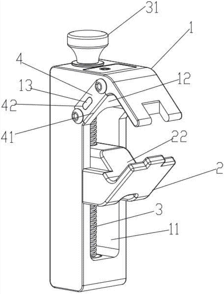
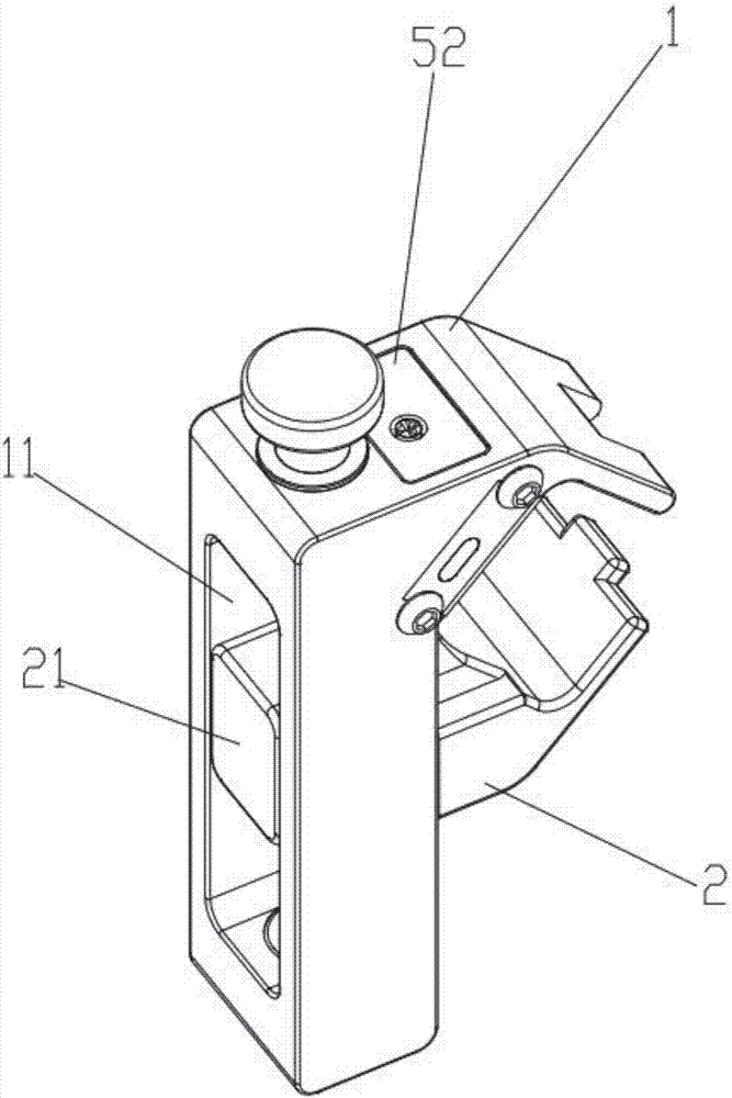
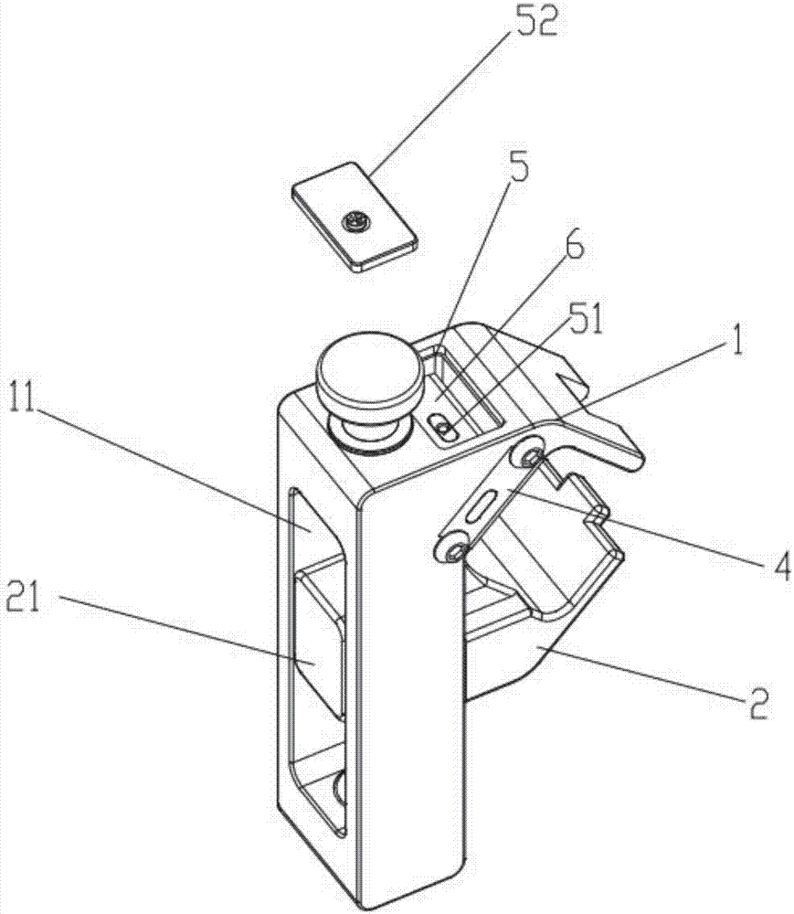
[0020] Such as figure 1 As shown, a cable stripping knife includes a first knife rest 1, a second knife rest 2 and an adjusting screw 3, one side of the first knife rest 1 is provided with a guiding straight groove 11, and one side of the second knife rest 2 is provided with There is a guide block 21 matched with the guide straight groove 11, the guide block 21 is embedded...


PUM


Abstract

The present invention relates to the field of cable knives, in particular to a cable cover-peeling knife which comprises a first knife rest, a second knife rest and an adjusting screw. One side of the second knife rest is provided with a guide straight groove; one side of the first knife rest is provided with a guide block which is embedded in the guide straight groove and capable of reciprocating movement; the adjusting screw goes through the guide straight groove to be in threaded connection with a guide block; both ends of the adjusting screw are respectively rotatably connected to the both ends of the guide straight groove; the first knife rest and the second knife rest are correspondingly provided with a first clamping surface and a second clamping surface; the first knife rest or the second knife rest is fixedly equipped with a chamfering blade; a chamfering cutting blade of the chamfering blade extends outside of the corresponding clamping surface; and an obtuse angle forms between the chamfering cutting blade and the corresponding clamping surface. The beneficial effects of the cable cover-peeling knife of the present invention are that the cable cover-peeling efficiency is high; the cover-peeling depth and angle are uniform; the cable internal structure can be effectively from being damaged in peeling; the cable cover-peeling knife is applicable to cables with different diameters; the universality is high; and the cable cover-peeling knife has a simple structure, and is safe and reliable.

Description

technical field [0001] The invention relates to the field of cable cutters, in particular to a cable stripping knife. Background technique [0002] When installing or overhauling power cables, it is necessary to peel off the cable sheath (including insulating layer, semi-conductive layer, copper shielding layer, outer sheath, etc.) to connect the line. Traditional cable stripping tools use electrician's knife, hook knife or Tools such as wallpaper knives are used to peel the skin, but because the blades of these knives are not installed firmly, they are easy to shake when cutting the cable skin, and the depth of the cut cable skin is uneven, especially when cutting the semi-conductive layer or copper shielding layer of the cable, due to the semi-conductive Layer and copper shielding layer are relatively thin, it is easy to penetrate the semi-conductive layer or copper shielding layer and destroy its internal structure when cutting, and because the copper shielding layer is r...

Claims


Application Information

Patent Timeline
IPC IPC(8): H02G1/12
CPCH02G1/1224
Inventor 胡超强尤占山孙建吉张泽桥覃丹陈雪儿卢广业张开拓王延发张仕欢郝燕邵源鹏程雪丽刘金勇
Owner GUANGZHOU PANYU CABLE WORKS
Features
  • R&D
  • Intellectual Property
  • Life Sciences
  • Materials
  • Tech Scout
  • Unparalleled Data Quality
  • Higher Quality Content
  • 60% Fewer Hallucinations
Learn More