Cable rack

A technology of cables and hangers, which is applied in the direction of pipe supports, hoses, pipes, etc., can solve the problems of cable wear, high failure rate, and inconvenient maintenance of cable hangers, and achieve the effect of reducing failure rate and long service life

Pending Publication Date: 2017-11-10
LAIWU IRON & STEEL GRP
View PDF15 Cites 0 Cited by
  • Summary
  • Abstract
  • Description
  • Claims
  • Application Information

AI Technical Summary

Problems solved by technology

In the prior art, insulating porcelain bottles and ordinary pulleys are usually used as cable hangers and hung on steel cables. However, due to the certain flexibility of the cables, this causes accelerated wear of the cable hangers and a high failure rate. Most of the cables are overhead cables. For example, the cables of simple cranes are generally installed at a height of more than 5 meters, which makes the maintenance of cable hangers very inconvenient.

Method used


Image

  • Cable rack
  • Cable rack
  • Cable rack

Examples


Embodiment Construction

[0037] In order to make the objectives, technical solutions and advantages of the present invention clearer, the technical solutions of the present invention will be described clearly and completely in conjunction with specific embodiments of the present invention and the corresponding drawings. Obviously, the described embodiments are only a part of the embodiments of the present invention, rather than all the embodiments. Based on the embodiments of the present invention, all other embodiments obtained by those of ordinary skill in the art without creative work shall fall within the protection scope of the present invention.

[0038] The technical solutions provided by the embodiments of the present invention will be described in detail below with reference to the accompanying drawings.

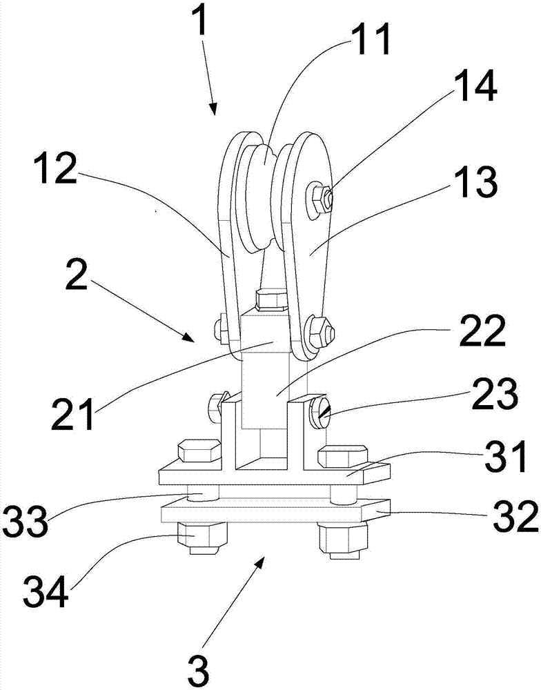
[0039] figure 1 It is a perspective view of the assembly structure of the cable hanger provided by an embodiment of the present invention. Such as figure 1 As shown, the cable hanger of the emb...


PUM


Abstract

The invention provides a cable rack which comprises a suspension guide mechanism, a universal rotating mechanism and a cable fixing mechanism; wherein the suspension guide mechanism comprises a pulley, a first chain plate, a second chain plate and a first hinge pin; the universal rotating mechanism comprises a cross beam, a hanger and a second hinge pin; the cable fixing mechanism comprises a suspension part, a press plate, a screw bolt and a nut; the cross beam comprises a first cross arm shaft, a second cross arm shaft and a cross beam body; the first cross arm shaft and the second cross arm shaft are in rotation connection with the first chain plate and the second chain plate respectively, and the cross beam takes the first cross arm shaft and the second cross arm shaft as the axes to rotate; the hanger comprises a rotation shaft and a hanger body, the rotation shaft is in rotation connection with the cross beam, and the hanger takes the rotation shaft as the axis to rotate; the suspension part is in rotation connection to the hanger by the second hinge pin, and the cable fixing mechanism swings around the second hinge pin. According to the cable rack, the cable flexibility can be offset, and the fault rate of the cable hanger can be reduced.

Description

Technical field [0001] The invention relates to the technical field of cable installation, in particular to a cable hanger. Background technique [0002] Simple lifting equipment, ordinary machine tools and other equipment have mobile cables, and these occasions are not suitable for installing cable trays. In the prior art, insulating porcelain bottles and ordinary pulleys are usually used as cable hangers and suspended on steel cables. However, because the cables have certain flexibility, this causes accelerated wear of the cable hangers and high failure rate. Most of the cables are overhead cables. For example, cables of simple cranes are generally installed at a height of more than 5 meters, which leads to inconvenient maintenance of cable hangers. [0003] Therefore, how to reduce the flexibility of the cable and reduce the failure rate of the cable hanger has become an urgent technical problem to be solved by those skilled in the art. Summary of the invention [0004] The inv...

Claims


Application Information

Patent Timeline
Patent Type & Authority Applications(China)
IPC IPC(8): F16L3/01
CPCF16L3/012
Inventor 王书涛李开伦胡广庆齐文韬刘学猛冯经虞李晓宾梁栋
Owner LAIWU IRON & STEEL GRP
Why Eureka
Try Eureka