
Device and method for controlling synchronous rectifier

A synchronous rectification and control circuit technology, applied in output power conversion devices, control/regulation systems, DC power input conversion to DC power output, etc., can solve problems such as false triggering

Active Publication Date: 2017-11-10
CHENGDU MONOLITHIC POWER SYST
View PDF4 Cites 18 Cited by
  • Summary
  • Abstract
  • Description
  • Claims
  • Application Information

AI Technical Summary

Problems solved by technology

However, this control method often leads to false triggering due to the oscillation of the drain-source voltage of the secondary rectifier.

Method used


Image

  • Device and method for controlling synchronous rectifier
  • Device and method for controlling synchronous rectifier
  • Device and method for controlling synchronous rectifier

Examples


Embodiment Construction

[0026] The specific embodiments of the present invention will be described in detail below. It should be noted that the embodiments described herein are only used for illustration and are not used to limit the present invention. In the following description, numerous specific details are set forth in order to provide a thorough understanding of the present invention. It will be apparent, however, to one of ordinary skill in the art that these specific details need not be employed to practice the present invention. In other instances, well-known circuits, materials, or methods have not been described in detail in order to avoid obscuring the present invention.

[0027] Throughout this specification, references to "one embodiment," "an embodiment," "an example," or "an example" mean that a particular feature, structure, or characteristic described in connection with the embodiment or example is included in the present invention in at least one embodiment. Thus, appearances of ...


PUM


Abstract

The invention discloses a device and a method for controlling a synchronous rectifier. The conversion rate of the switching voltage across the two ends of a secondary switch is detected in order to prevent the secondary switch from being triggered falsely due to switching voltage oscillation. The circuit includes a secondary switch coupled to an energy storage element, and a secondary control circuit. The secondary control circuit receives the switching voltage across the two ends of the secondary switch and a conversion rate threshold adjustment signal, and outputs a secondary switch control signal to control on-off of the secondary switch. When the conversion rate of the switching voltage is lower than a preset conversion rate threshold, the secondary switch control signal makes the secondary switch switched off.

Description

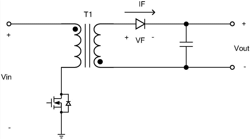
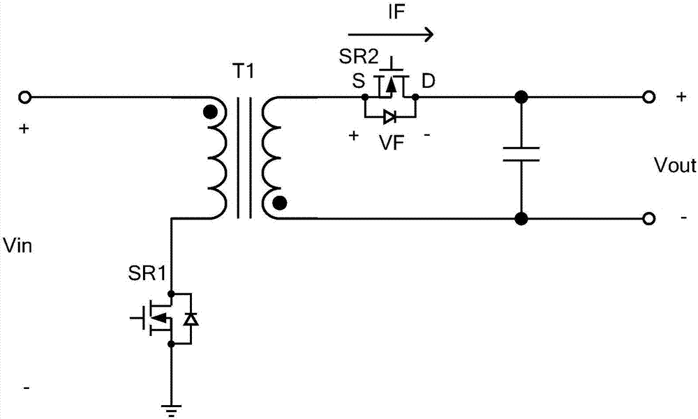
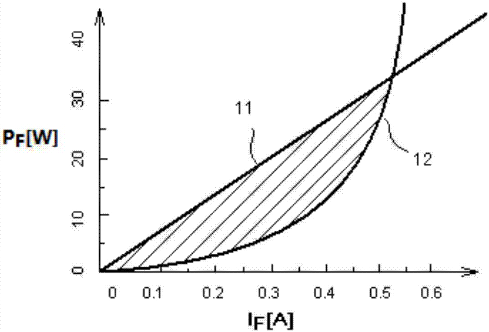
technical field [0001] The invention relates to a switching power supply circuit, in particular to the control of a secondary side synchronous rectifier. Background technique [0002] There are currently two types of secondary-side rectification schemes for flyback switching power supplies, one is asynchronous rectification, that is, using diodes (such as Figure 1A shown), the other is synchronous rectification (such as Figure 1B shown). Synchronous rectification uses the gate drive signal to control the turn-on and turn-off of the synchronous rectifier SR2 to achieve rectification. figure 2 The curves show the power dissipation characteristics of diodes and synchronous rectifiers. In practical applications, the operating range of the low-power flyback switching power supply is in the shaded range. In this interval, the power consumption characteristic curve 12 of the synchronous rectifier is below the power consumption characteristic curve 11 of the diode, that is, th...

Claims


Application Information

Patent Timeline
IPC IPC(8): H02M3/335
CPCH02M3/33592H02M1/08Y02B70/10
Inventor 李晖缪磊王斯然冯林
Owner CHENGDU MONOLITHIC POWER SYST
Learn More