Constant fraction timing discriminator circuit

A constant-ratio timing identification and circuit technology, applied in electrical components, pulse processing, pulse technology, etc., can solve problems such as reduced timing accuracy, delayed signal distortion, and difficulties, so as to improve stability and reliability, reduce noise, etc. The effect of reducing the effective bandwidth and reducing the timing error

Active Publication Date: 2015-03-11
NAT UNIV OF DEFENSE TECH
View PDF3 Cites 0 Cited by
  • Summary
  • Abstract
  • Description
  • Claims
  • Application Information

AI Technical Summary

Problems solved by technology

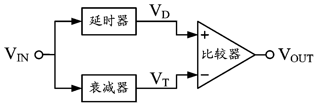
Using a delay line to implement a delayer has the advantages of small signal distortion and high time discrimination accuracy, but has the disadvantages of large size, difficult integration and relatively difficult adjustment.
Replacing the delay line with a linear network such as a resistor-inductor low-pass filter, a resistor-capacitor low-pass filter or a high-pass filter has the advantages of small size, easy integration and convenient adjustment, but the delay signal is distorted, which reduces the timing accuracy.

Method used


Image

  • Constant fraction timing discriminator circuit
  • Constant fraction timing discriminator circuit
  • Constant fraction timing discriminator circuit

Examples


Embodiment Construction

[0043] Figure 5It is a logical structure diagram of the constant ratio timing discrimination circuit of the present invention. The constant-ratio timing discriminator circuit consists of a buffer, a pre-discriminator, a constant-ratio timing discriminator and a signal synthesizer. The input terminal of the buffer is connected with the external input pulse signal V IN connected, the buffer to V IN After power amplification and driving capability enhancement, the output signal V B . The output of the buffer is connected to the input of the pre-discriminator and constant-ratio timing discriminator. The input of the pre-discriminator is connected to the signal V B and reference voltage V REF , the pre-discriminator on the signal V B Make a judgment to determine whether there is a pulse signal. The output signal of the pre-discriminator is the judgment result signal V P , the output of the pre-discriminator is connected to the input of the signal synthesizer. The input o...


PUM


Abstract

The invention discloses a constant fraction timing discriminator circuit, and aims to improve the timing accuracy and the reliability. The constant fraction timing discriminator circuit consists of a buffer, a pre-discriminator, a constant fraction timing discriminator and a signal synthesizer; the buffer outputs VB to the pre-discriminator and the constant fraction timing discriminator after performing power amplification and drive capability enhancement on VIN; the pre-discriminator judges the VB, and outputs a result VP to the signal synthesizer; the constant fraction timing discriminator determines a timing point according to the VB, and outputs a timing signal VC to the signal synthesizer; the signal synthesizer generates a timing signal VOUT according to the VP and the VC; the constant fraction timing discriminator consists of a delayer, a low-pass filter and a first comparator; the low-pass filter adopts a first-order, multi-order resistance-capacitance (RC) or resistance-inductance-capacitance (RLC) low-pass filter; the delayer adopts a multi-level inductance-capacitance (LC) or resistance-inductance-capacitance (RLC) network; and the low-pass filter and the delayer set the timing point at a peak point of a reference signal or at the slope maximal point of a rising edge of a delay signal. The constant fraction timing discriminator circuit is high in stability, reliability and accuracy, small in size, easy to integrate and convenient to adjust.

Description

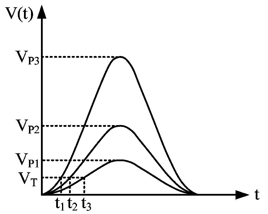
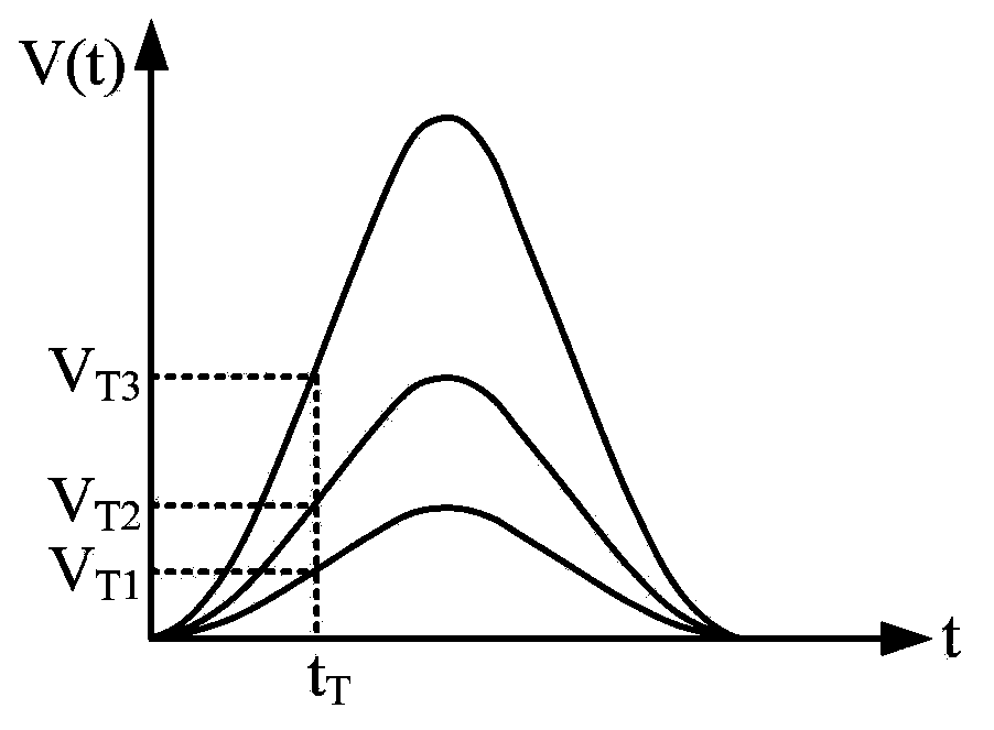
technical field [0001] The invention relates to a timing identification circuit, in particular to a constant-ratio timing identification circuit used for pulse signal time identification. Background technique [0002] In the laser range finder and three-dimensional imaging lidar based on laser pulse time-of-flight ranging, the amplitude of the echo laser pulse signal of the target will change due to changes in the distance, reflectivity and attitude of the target, which will cause the photoelectric detection circuit to detect The amplitude of the electrical pulse signal changes accordingly. If a fixed threshold timing identification circuit is used to identify the timing of the electric pulse signal, the amplitude variation of the pulse signal will produce a large timing error. figure 1 It is a schematic diagram of the principle of discriminating the pulse signal for the fixed threshold timing discrimination circuit, figure 1 , the signals are amplitudes of V P1 , V P2 ,...

Claims


Application Information

Patent Timeline
Patent Type & Authority Patents(China)
IPC IPC(8): H03K5/1252
Inventor 胡春生秦石乔王省书黄宗升战德军
Owner NAT UNIV OF DEFENSE TECH
Why Eureka
Try Eureka