Terminal and acoustic wave signal transmission method

A sound wave signal and terminal technology, applied in ultrasonic/sonic/infrasonic transmission system, transmission system, sound wave re-radiation, etc., can solve the problems of high device cost and large space occupied by the circuit

Inactive Publication Date: 2017-11-10
BEIJING XIAOMI MOBILE SOFTWARE CO LTD
View PDF4 Cites 7 Cited by
  • Summary
  • Abstract
  • Description
  • Claims
  • Application Information

AI Technical Summary

Problems solved by technology

[0005] Since the devices used to realize the handset function and the distance detection function are different, the corresponding hardware circuits are also different, so two sets of hardware circuits are required in the terminal, one set corresponds to the physical function of the handset, and the other corresponds to the physical function of distance detection. function, resulting in high device cost and large space occupied by each circuit

Method used


Image

  • Terminal and acoustic wave signal transmission method
  • Terminal and acoustic wave signal transmission method
  • Terminal and acoustic wave signal transmission method

Examples


Embodiment Construction

[0061] Reference will now be made in detail to the exemplary embodiments, examples of which are illustrated in the accompanying drawings. When the following description refers to the accompanying drawings, the same numerals in different drawings refer to the same or similar elements unless otherwise indicated. The implementations described in the following exemplary examples do not represent all implementations consistent with the present disclosure. Rather, they are merely examples of apparatuses and methods consistent with aspects of the present disclosure as recited in the appended claims.

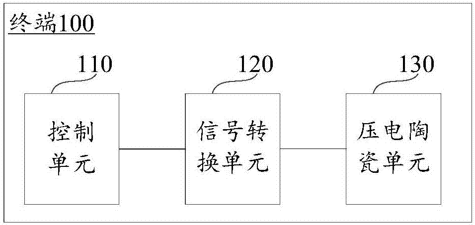
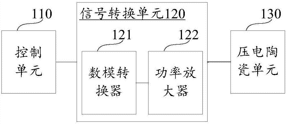
[0062] figure 1 It is a schematic structural diagram of a terminal shown according to an exemplary embodiment. Such as figure 1 As shown, the terminal 100 includes a control unit 110 , a signal conversion unit 120 and a piezoelectric ceramic unit 130 .

[0063] The control unit 110 is connected to the signal conversion unit 120 , the signal conversion unit 120 is connected to the pi...


PUM


Abstract

The invention relates to a terminal and an acoustic wave signal transmission method and belongs to the technical field of the terminal. The terminal comprises a control unit, a signal conversion unit and a piezoelectric ceramic unit. The control unit is connected with the signal conversion unit. The signal conversion unit is connected with the piezoelectric ceramic unit. The piezoelectric ceramic unit is fixed on a machine body of the terminal. The control unit is used for outputting a digital signal corresponding to an acoustic wave signal. The signal conversion unit is used for converting the digital signal into an analog signal. The piezoelectric ceramic unit is used for carrying out vibration according to the analog signal and driving the machine body of the terminal to vibrate, thereby sending the acoustic wave signal. The acoustic wave signal comprises at least one of a voice acoustic wave signal and an ultrasonic wave signal. According to the terminal and the method, the problem that a device cost is high and a circuit occupied space is large due to the fact that two sets of hardware circuits are employed when a mobile phone telephone receiver function and a distance detection function are realized is solved, devices are reduced, and the circuit occupied space is reduced.

Description

technical field [0001] The present disclosure relates to the technical field of terminals, and in particular, to a terminal and an acoustic signal transmission method. Background technique [0002] There are many devices arranged on the front panel of the mobile phone to realize different functions of the mobile phone, such as a handset, a distance detector, and the like. The earpiece is used to transmit the sound signal to the outside when answering the phone. The distance detector is used to detect the distance between the external object and the mobile phone. When the user answers the call or puts the mobile phone in the pocket, the distance detector judges that the mobile phone is close to the face or clothes and turns off the touch function of the screen to avoid misuse. [0003] Usually the handset of a mobile phone uses a thin-film speaker. The earpiece contains a thin film, which is connected to a coil. The position of the coil can be changed. In addition, there is ...

Claims


Application Information

Patent Timeline
IPC IPC(8): H04M1/03H04M1/02H04M1/725H04B11/00G01S15/08G01S7/534G01S7/526
CPCG01S7/526G01S7/534G01S15/08H04B11/00H04M1/026H04M1/03H04M1/72454
Inventor 李以龙廖柏树
Owner BEIJING XIAOMI MOBILE SOFTWARE CO LTD
Why Eureka
Try Eureka