Fluorescent quantitative analysis meter

A fluorescence quantitative and analyzer technology, which is applied in the direction of analyzing materials, fluorescence/phosphorescence, and material analysis through optical means, can solve the problems of complex mechanical transmission structure of the analyzer and low utilization rate of optical path devices, etc. Scalable effects

Active Publication Date: 2018-06-19
王碧
View PDF5 Cites 6 Cited by
  • Summary
  • Abstract
  • Description
  • Claims
  • Application Information

AI Technical Summary

Problems solved by technology

[0004] In view of the above problems, what the present invention is to solve is to provide a fluorescent quantitative analyzer with compact structure, portable and easy to use, which can analyze and detect human blood and urine based on the principle of fluorescence immunity and immunochromatography technology, and solve the problem of existing analyzers. The technical problems of complex mechanical transmission structure and low utilization rate of optical components

Method used


Image

  • Fluorescent quantitative analysis meter
  • Fluorescent quantitative analysis meter
  • Fluorescent quantitative analysis meter

Examples


Embodiment 1

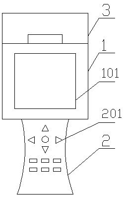
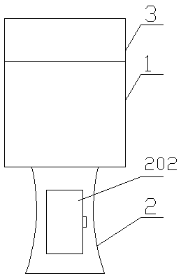
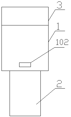
[0058] Such as figure 1 As shown, a fluorescence quantitative analyzer comprises a fuselage 1, a thermal printer 3 installed on the top of the fuselage 1, and a fishtail handle 2 installed on the bottom of the fuselage 1, wherein: the fuselage 1 is a hollow cuboid structure, and the machine The front of the body 1 is provided with a liquid crystal screen 101 for displaying data, and the side of the body 1 is provided with a detection inlet 102 for placing the object to be inspected; the front of the fishtail handle 2 is provided with a keyboard 201 for information interaction. The back side of the body 1 is provided with a battery box 202 for placing batteries, and the position of the battery box 202 is as follows: figure 2 shown. Specifically, the thermal printer 3 can print the detection data.

[0059] Such as image 3 , 4 As shown, it also includes a detection card 4 for inserting into the detection inlet 102, and the detection card 4 includes a detection board 401, a ...

Embodiment 2

[0078] Such as Figure 13 , Figure 14 As shown, this embodiment expands the detection optical fiber that can be connected externally on the basis of the first embodiment, which can be directly used for the measurement of the external reaction tank of the analyzer, and is suitable for pesticide detection and seaweed detection. Specifically, an optical fiber interface 103 is also provided on the side of the fuselage 1 corresponding to the location of the optical fiber collection. This embodiment also includes an optical fiber bundle 14 detachably connected to the optical fiber interface 103, and one end of the optical fiber bundle 14 is connected to the collection optical fiber through a connector 15. The other end of the optical fiber bundle 14 is connected to the optical fiber probe 16 through the connector 15 . Specifically, the connector 15 can connect multi-mode plastic optical fiber bundles, single-mode optical fibers and optical fiber probes, so as to generate transmiss...

Embodiment 3

[0085] Compared with Embodiment 2, the structure of the collecting fiber in Embodiment 3 is different, such as Figure 20 As shown, the third embodiment includes a vertical collecting optical fiber 13, a second fluorescence sensor 11 and two groups of coupling assemblies 10, and the side of the fuselage 1 is also provided with an optical fiber interface 103 at a position corresponding to the collecting optical fiber. Figure 21 As shown, the vertical collection fiber 13 includes a vertical incident fiber 1301 and a vertical receiving fiber 1302 parallel to each other, and a vertical collection end perpendicular to the vertical incident fiber 1301 and the vertical receiving fiber 1302 respectively, and the vertical incident fiber 1301 is used for collecting input light source 701, the vertical receiving fiber 1302 is used to lead out fluorescence, and the vertical summarizing end 1303 is installed in the fiber interface 103 and used to collect the vertical incident fiber 1301 an...


PUM


Abstract

The invention provides a fluorescent quantitative analysis meter and relates to the technical field of medical detecting instruments. The fluorescent quantitative analysis meter comprises a machine body, a thermal printer arranged at the top of the machine body and a fishtail handle arranged at the bottom of the machine body, wherein the machine body is of a hollow rectangular solid structure, a liquid crystal display screen used for displaying data is arranged on the front of the machine body, and a detection entrance used for placing a to-be-detected object is formed in the side surface of the machine body; and a keyboard used for information interaction is arranged on the front of the fishtail handle, and a battery holder used for placing a battery is arranged on the back of the machinebody. The fluorescent quantitative analysis meter provided by the invention is compact in structure, portable and easy to use, human blood and urine are analyzed and detected based on fluorescence immunoassay and immunochromatography technical principles, and the technical problems that a mechanical transmission structure of an existing analysis meter is complex and utilization rate of an opticalcircuit device is low are solved.

Description

technical field [0001] The invention relates to the technical field of medical detection instruments, in particular to a fluorescence quantitative analyzer. Background technique [0002] Fluorescence immunoassay (FIA) is a microanalysis method developed in recent years, and it is one of the most sensitive microanalysis techniques at present. Molecules of certain substances can absorb energy and emit fluorescence. According to the fluorescence spectrum and fluorescence intensity, the method of qualitative or quantitative substance is called fluorescence analysis. Fluorescence immunoassay (FIA) has the advantages of high sensitivity, strong selectivity, less sample required, and simple method. The lower limit of determination of this method is usually 2 to 4 orders of magnitude higher than that of spectrophotometry, and it is widely used in biochemical analysis. . [0003] The current general-purpose fluorescent quantitative detectors are usually bulky and not convenient for...

Claims


Application Information

Patent Timeline
Patent Type & Authority Applications(China)
IPC IPC(8): G01N21/64G01N21/01G01N33/558G01N33/533
CPCG01N21/01G01N21/6402G01N21/6486G01N33/533G01N33/558
Inventor 王碧蒋丽玲李静
Owner 王碧
Why Eureka
Try Eureka