Non-contact drilling fluid density sensor

A drilling fluid density, non-contact technology, applied in the field of sensors, can solve the problems of affecting the life of the sensor, affecting the measurement accuracy, and high impurity content, achieving the effects of simple structure, convenient use and cost saving

Inactive Publication Date: 2017-11-14
天津同创达科石油科技有限公司
View PDF6 Cites 1 Cited by
  • Summary
  • Abstract
  • Description
  • Claims
  • Application Information

AI Technical Summary

Problems solved by technology

[0002] In drilling operations, it is often necessary to measure the density of drilling fluid. Usually, drilling instruments or logging instruments contain density sensors; these sensors are all contact type, that is, the two diaphragm pressure transmitter bodies used It needs to be in contact with the drilling fluid, and its basic principle is the differential pressure method; due to the complex characteristics of the drilling fluid, which has the characteristics of high impurity content and high viscosity, the mud will form deposition or adhesion on the surface of the sensor diaphragm after long-term use, which is It is necessary to clean the surface of the diaphragm frequently, otherwise it will greatly affect the measurement accuracy; in addition, due to the high corrosiveness of the drilling fluid, it will cause irreversible damage to the diaphragm, which greatly affects the life of the sensor

Method used


Image

  • Non-contact drilling fluid density sensor
  • Non-contact drilling fluid density sensor

Examples


Embodiment Construction

[0015] The following will clearly and completely describe the technical solutions in the embodiments of the present invention with reference to the accompanying drawings in the embodiments of the present invention. Obviously, the described embodiments are only some, not all, embodiments of the present invention.

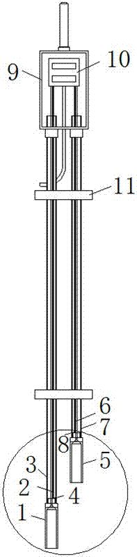
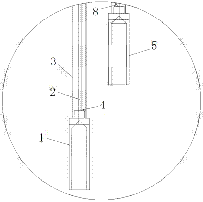
[0016] refer to Figure 1-2 , the present embodiment proposes a non-contact drilling fluid density sensor, including a deep probe 1 and a shallow probe 5, the air guide hole of the deep probe 1 and the air guide hole of the shallow probe 5 are respectively sealed and connected with the deep probe capillary air guide tube 2 and the shallow probe capillary The air guide tube 6, and the deep probe 1 and the shallow probe 5 are respectively sealed and threaded with the deep probe anti-pressure tube 3 and the shallow probe anti-pressure tube 7, and the deep probe capillary air tube 2 and the shallow probe capillary air tube 6 are connected from the deep probe anti-pressure...


PUM


Abstract

The invention discloses a non-contact drilling fluid density sensor, which comprises a deep probe and a shallow probe. A gas-guide hole of the deep probe and a gas-guide hole of the shallow probe are respectively connected with a deep probe capillary gas-guide pipe and a shallow probe capillary gas-guide pipe in a sealing way; the deep probe and the shallow probe are respectively in threaded connection with a deep probe compression resistance pipe and a shallow probe compression resistance pipe in a sealing way; the deep probe capillary gas-guide pipe and the shallow probe capillary gas-guide pipe respectively penetrate through the inside part of the deep probe compression resistance pipe and the inside part of the shallow probe compression resistance pipe; a deep probe temperature sensor and a shallow probe temperature sensor are respectively arranged in the deep probe compression resistance pipe and the shallow probe compression resistance pipe. According to the non-contact drilling fluid density sensor provided by the invention, air isolation of drilling fluid and a pressure sensor is realized, accurate density calculation is realized by adopting a temperature compensation and non-linear correlation algorithm, and the non-contact drilling fluid density sensor is simple in structure, convenient to use and low in cost.

Description

technical field [0001] The invention relates to the technical field of sensors, in particular to a non-contact drilling fluid density sensor. Background technique [0002] In drilling operations, it is often necessary to measure the density of drilling fluid. Usually, drilling instruments or logging instruments contain density sensors; these sensors are all contact type, that is, the two diaphragm pressure transmitter bodies used It needs to be in contact with the drilling fluid, and its basic principle is the differential pressure method; due to the complex characteristics of the drilling fluid, which has the characteristics of high impurity content and high viscosity, the mud will form deposition or adhesion on the surface of the sensor diaphragm after long-term use, which is The surface of the diaphragm needs to be cleaned frequently, otherwise it will greatly affect the measurement accuracy; in addition, due to the high corrosiveness of the drilling fluid, it will cause ...

Claims


Application Information

Patent Timeline
IPC IPC(8): G01N9/26
CPCG01N9/26
Inventor 裴斐李海营邹庆波
Owner 天津同创达科石油科技有限公司
Why Eureka
Try Eureka