Supercharge Your Innovation With Domain-Expert AI Agents!

Generator brush current on-line monitoring system

A brush current and monitoring system technology, applied in the direction of measurement using digital measurement technology, can solve problems such as overheating disconnection, disconnection, increased carbon brush wear, etc., to achieve easy operation, simple system structure, and ensure stability and reliability running effect

Inactive Publication Date: 2017-11-14
STATE GRID CORP OF CHINA +2
View PDF2 Cites 3 Cited by
  • Summary
  • Abstract
  • Description
  • Claims
  • Application Information

AI Technical Summary

Problems solved by technology

After the carbon brush heats up, it is very easy to cause the disconnection of the joint between the carbon brush body and the copper wire. The disconnection of a single carbon brush will cause the current density of the remaining carbon brushes to increase. When the current density increases, the heat generated by the brush will increase significantly, which will affect Multiple brush bodies and copper wire joints are overheated and disconnected, which eventually leads to extensive damage to the carbon brushes, and the generator loses excitation and trips
In addition, when the temperature of the carbon brush body rises, the temperature of the spring element directly connected to it also increases significantly. Since the material of the spring element is a material with a positive temperature coefficient, the material stress changes when the temperature rises, and the spring that is too high or too low The pressure causes the carbon brush to jump under high-speed rotation, which increases the wear of the carbon brush and also makes the spring element easy to break
At present, there is no unified online test method in China to conduct a complete appraisal of its operation. Now it can only be used to check the joint between the carbon brush body and the copper wire during the maintenance of the unit.

Method used


Image

  • Generator brush current on-line monitoring system
  • Generator brush current on-line monitoring system
  • Generator brush current on-line monitoring system

Examples


Embodiment Construction

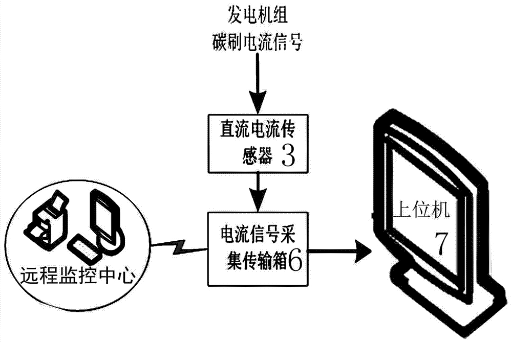
[0019] The present invention is an on-line monitoring system for generator brush current, such as figure 1 as shown, figure 1 It is the framework diagram of the generator carbon brush current distributed monitoring system. In the present invention, the DC current sensor 3 is fixedly installed on each carbon brush braid 4, and the DC current sensor 3 is connected to the current signal acquisition transmission box 6 through the shielded transmission line 5; the current signal acquisition transmission box 6 is connected to the upper computer 7 through the network cable , the other path of the current signal acquisition transmission box 6 is directly sent to the remote monitoring center by the wireless transmitting module after being converted by the serial port.

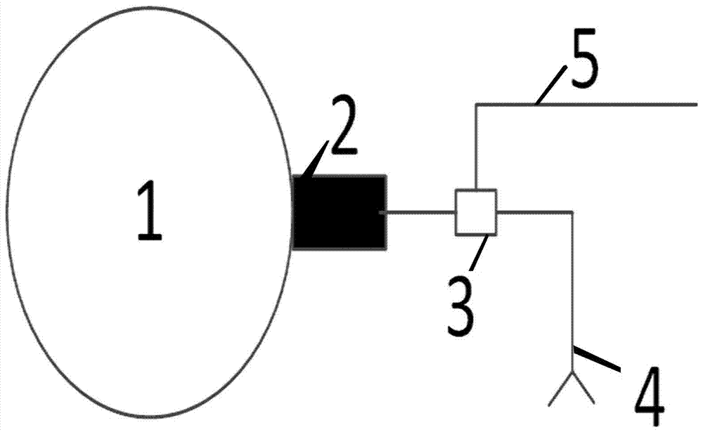
[0020] Such as figure 2 as shown, figure 2 Schematic diagram of the installation position of the DC current sensor. The DC current sensor 3 is fixedly connected to the carbon brush pigtail 4, and is indirectly ele...


PUM


Abstract

The invention belongs to the technical field of industrial automation, in particular to the technical field of a method for testing the running condition of a generator rotor collector ring carbon brush, and in particular to an online monitoring system for generator brush current. The DC current sensor is connected to each carbon brush pigtail, and the DC current sensor is connected to the current signal acquisition transmission box through a shielded transmission line; one end of the current signal acquisition transmission box is connected to the host computer through a network cable, and the other end of the current signal acquisition transmission box One end is directly connected to the remote monitoring center by the wireless transmitting module after serial port conversion. The system of the invention has simple structure and is easy to operate. Through the setting of the non-contact DC current sensor, the current passing through each group of carbon brushes can be monitored in real time, which is convenient for the on-duty personnel to find defects, and a fault alarm signal can be sent out when there is a brush disconnection fault, so that the on-duty personnel can make corresponding adjustments in time , to ensure the stable and reliable operation of the generator rotor collector ring carbon brush.

Description

technical field [0001] The invention belongs to the technical field of industrial automation, in particular to the technical field of a method for testing the running condition of a generator rotor collector ring carbon brush, and in particular to an online monitoring system for generator brush current. Background technique [0002] In recent years, most of the domestic pumped storage units start and stop frequently and run for a long time. The main differences from conventional units are: the units operate with high water head and high speed, and the daily fluctuation of upstream and downstream water levels is large. Frequent, etc., under the high-speed friction between the collector ring and the carbon brush and the action of the electromagnetic field, the carbon brush of the generator motor is prone to overheating and ignition failure. After the carbon brush heats up, it is very easy to cause the disconnection of the joint between the carbon brush body and the copper wire...

Claims


Application Information

Patent Timeline
IPC IPC(8): G01R19/25
CPCG01R19/25
Inventor 吕鹏飞
Owner STATE GRID CORP OF CHINA
Features
  • R&D
  • Intellectual Property
  • Life Sciences
  • Materials
  • Tech Scout
  • Unparalleled Data Quality
  • Higher Quality Content
  • 60% Fewer Hallucinations
Learn More