Roller motor and use method thereof

A drum motor and drum technology, applied in the direction of electrical components, electromechanical devices, electric components, etc., can solve problems such as troubles, achieve the effect of ensuring normal operation and reducing parts

Pending Publication Date: 2017-11-14
SHENZHEN RUOTENG TECH CO LTD
View PDF0 Cites 7 Cited by
  • Summary
  • Abstract
  • Description
  • Claims
  • Application Information

AI Technical Summary

Problems solved by technology

[0003] The motors on the market now generally rotate on a rotating shaft. When in use, they also need to work with other parts such as belts, which is quite troublesome.

Method used


Image

  • Roller motor and use method thereof
  • Roller motor and use method thereof
  • Roller motor and use method thereof

Examples


Embodiment Construction

[0053] The present invention will be further described below with reference to the accompanying drawings and embodiments.

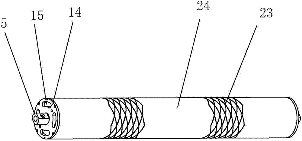
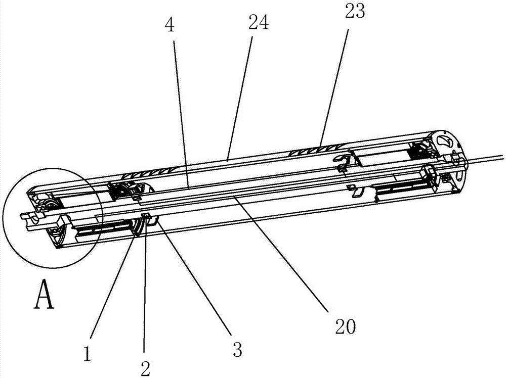
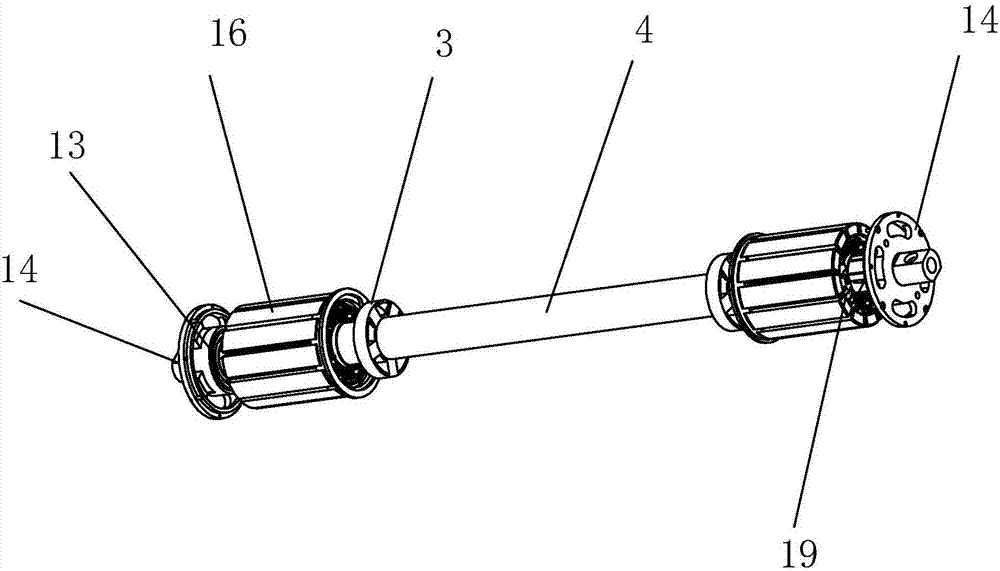
[0054] like Figure 1-Figure 11 As shown, a drum motor in this embodiment is characterized in that, the drum motor includes:

[0055] fixed shaft;

[0056] bearing assemblies arranged at both ends of the fixed shaft for bearing radial load;

[0057] a drum 24 arranged outside the fixed shaft and rotatable around the fixed shaft through the bearing assembly;

[0058] a stator assembly arranged on the fixed shaft;

[0059] and a rotor assembly disposed on the drum 24 and opposite to the stator assembly.

[0060] When the embodiment of the present invention is in use, the stator assembly is energized to make it interact with the rotor assembly, and the mutual rotation of the two is completed through the principle that the energized conductor can generate a force in the excitation magnetic field. Here, the rotor assembly is arranged on the inner side wal...


PUM


Abstract

The invention relates to a drum motor and its use method, comprising a fixed shaft; a bearing assembly arranged at both ends of the fixed shaft for bearing radial load; arranged outside the fixed shaft, the bearing assembly can A drum rotating around a fixed shaft; a stator assembly arranged on the fixed shaft; and a rotor assembly arranged on the drum and opposite to the stator assembly. With the above design, some components can be reduced when the motor is applied , quite convenient, and at the same time, the fan blade is designed in the motor, which can dissipate the heat in the drum motor in time.

Description

technical field [0001] The invention relates to the field of electrical appliances, in particular to a roller motor and a method for using the same. Background technique [0002] A motor is a device that converts electrical energy into mechanical energy. It uses the energized coil (that is, the stator winding) to generate a rotating magnetic field and acts on the rotor (such as a squirrel-cage closed aluminum frame) to form a magneto-electric rotational torque. Motors are divided into DC motors and AC motors according to different power sources. Most of the motors in the power system are AC motors, which can be synchronous motors or asynchronous motors (the stator magnetic field speed of the motor and the rotor rotation speed do not maintain a synchronous speed). The motor is mainly composed of a stator and a rotor, and the direction of the energized wire in the magnetic field is related to the direction of the current and the direction of the magnetic field line (magnetic ...

Claims


Application Information

Patent Timeline
Patent Type & Authority Applications(China)
IPC IPC(8): H02K7/00H02K5/16H02K9/04
CPCH02K7/00H02K5/165H02K9/04
Inventor 钟俊豪刘铭
Owner SHENZHEN RUOTENG TECH CO LTD
Why Eureka
Try Eureka