Emergency stop device of mechanical equipment

A technology for mechanical equipment and stopping devices, applied in mechanical equipment, engineering emergency devices, etc., can solve problems such as affecting the normal use of equipment, inconvenient equipment emergency stop processing, and reducing friction coefficient, achieving simple structure, high practical performance, and rapid realization. The effect of stopping processing

Inactive Publication Date: 2017-11-17
刘丽华
View PDF1 Cites 11 Cited by
  • Summary
  • Abstract
  • Description
  • Claims
  • Application Information

AI Technical Summary

Problems solved by technology

[0002] The emergency stop device, as the name implies, means that when an emergency occurs, people can activate the emergency stop device to achieve protection measures. The emergency stop device can quickly stop the entire equipment or release some transmission parts. It is required in industrial safety. The transmission parts will directly or indirectly cause harm to the human body in the event of an abnormal situation. Therefore, when designing some machines with transmission parts, an emergency stop device must be provided. The patent number is CN 102804304 A The patent document provides an emergency stop device. In this structure, the contact position of the first brake body on the guide rail and the contact position of the second brake body on the guide rail are staggered from each other in the horizontal direction, so that the second brake body can be avoided. Open the sliding surface of the first braking body that slides relative to the guide rail and slide relative to the guide rail, thereby preventing the first braking body from sliding on the sliding surface that becomes high in temperature due to the sliding of the second braking body, thereby preventing 1. Since the coefficient of friction of the brake body with respect to the guide rail is reduced, not only the braking force of the second emergency stop mechanism part but also the braking force of the first emergency stop mechanism part can be generated more reliably, thereby realizing the operation of the emergency stop device The improvement of the reliability of the equipment, but in this structure, the operation of the emergency stop of the equipment is more troublesome, and it is not convenient to quickly stop the equipment, which will affect the normal use of the equipment. Therefore, we propose the emergency stop of the mechanical equipment. The stopping device is used to solve the above problems

Method used


Image

  • Emergency stop device of mechanical equipment
  • Emergency stop device of mechanical equipment
  • Emergency stop device of mechanical equipment

Examples


Embodiment

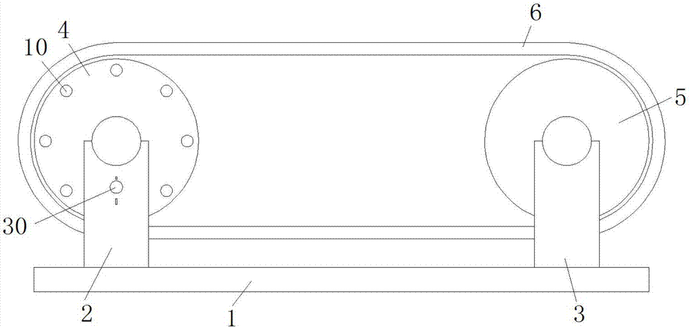
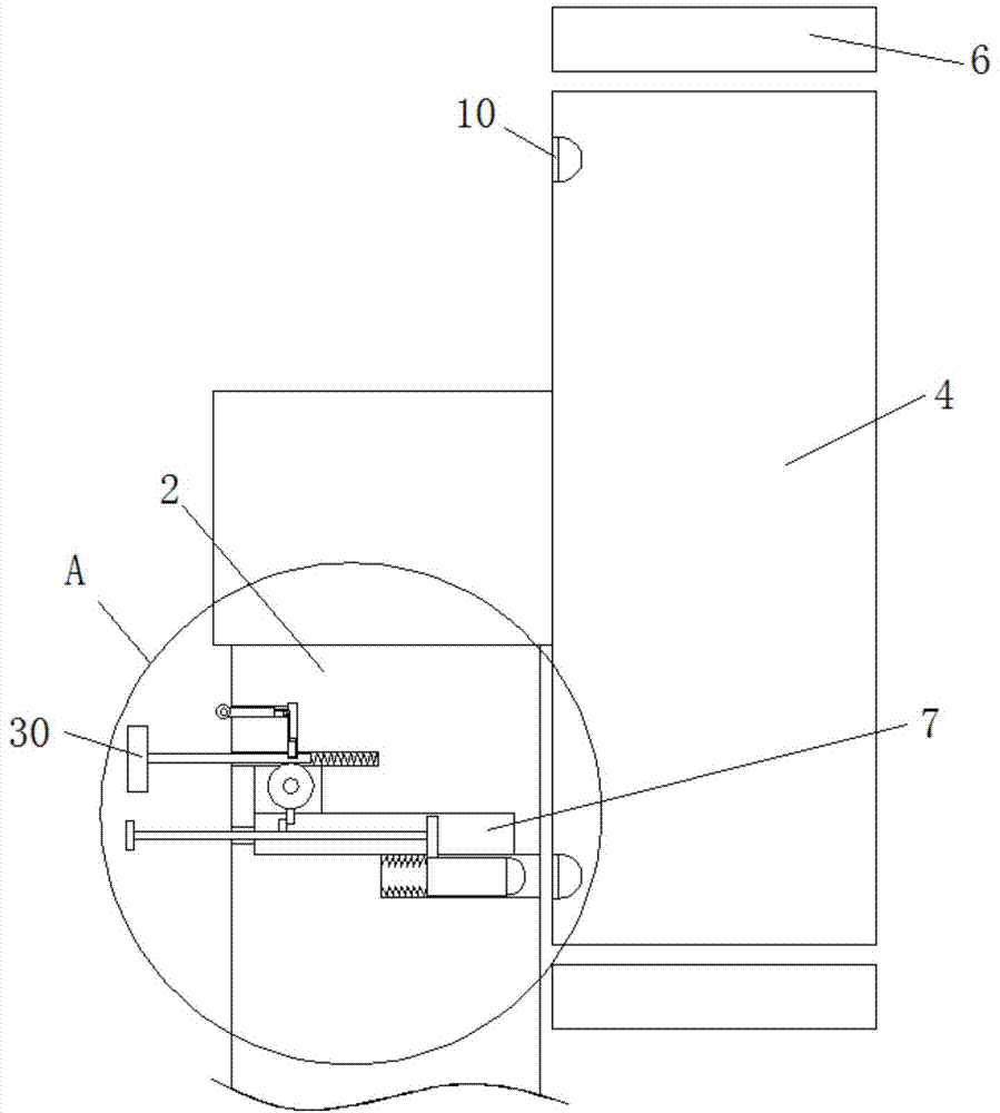
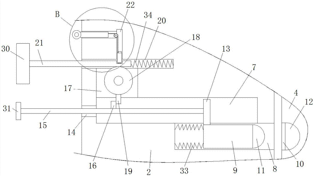
[0024] refer to Figure 1-5 In this embodiment, an emergency stop device for mechanical equipment is proposed, including a base 1, a first support 2 and a second support 3 are respectively welded on both sides of the top of the base 1, and the bottom ends of the first support 2 and the second support 3 are respectively The driving wheel 4 and the driven wheel 5 are installed in rotation, and the same conveyor belt 6 is installed on the driving wheel 4 and the driven wheel 5. The side of the first pillar 2 close to the driving wheel 4 has a limiting groove 8, and the sliding in the limiting groove 8 The limiting column 9 is installed, and the side of the driving wheel 4 close to the first pillar 2 is provided with a plurality of cylindrical grooves 10. A hemispherical clamping block 11 is welded, and a hemispherical clamping groove 12 is provided on the inner wall of the cylindrical groove 10 away from the first pillar 2, and the hemispherical clamping groove 12 is matched with...


PUM


Abstract

The invention discloses an emergency stop device for mechanical equipment, which comprises a base, a first support and a second support are respectively welded on both sides of the top of the base, and drive wheels are respectively installed on the bottom ends of the first support and the second support. and the driven wheel, the same conveyor belt is installed on the driving wheel and the driven wheel, the side of the first pillar close to the driving wheel is provided with a limiting groove, and a limiting column is slidably installed in the limiting groove, and the driving The side of the wheel close to the first pillar is provided with a plurality of columnar grooves, the columnar grooves are adapted to the limiting column, and the side of the limiting column close to the driving wheel is welded with a hemispherical block. The present invention has high practical performance, simple structure, convenient operation, is convenient to release the fixation of the drawbar, and is convenient to move the limit column, so that the hemispherical block is inserted into the hemispherical slot, and the drive wheel is fixed, realizing the Emergency stop processing of the conveyor belt.

Description

technical field [0001] The invention relates to the technical field of emergency stop devices, in particular to emergency stop devices for mechanical equipment. Background technique [0002] The emergency stop device, as the name implies, means that when an emergency occurs, people can activate the emergency stop device to achieve protection measures. The emergency stop device can quickly stop the entire equipment or release some transmission parts. It is required in industrial safety. The transmission parts will directly or indirectly cause harm to the human body in the event of an abnormal situation. Therefore, when designing some machines with transmission parts, an emergency stop device must be provided. The patent number is CN 102804304 A The patent document provides an emergency stop device. In this structure, the contact position of the first brake body on the guide rail and the contact position of the second brake body on the guide rail are staggered from each other ...

Claims


Application Information

Patent Timeline
Patent Type & Authority Applications(China)
IPC IPC(8): F16P7/00
CPCF16P7/00
Inventor 刘丽华
Owner 刘丽华
Why Eureka
Try Eureka