
Gothic groove supporting device of mass center measurement equipment

A technology of measuring equipment and supporting device, applied in the field of measurement, can solve the problems affecting the accuracy of the measurement, poor stability, etc., and achieve the effect of ensuring the accuracy, the same life, and reducing the lateral force.

Inactive Publication Date: 2017-11-17
HARBIN INST OF TECH
View PDF4 Cites 1 Cited by
  • Summary
  • Abstract
  • Description
  • Claims
  • Application Information

AI Technical Summary

Problems solved by technology

[0011] In order to solve the problem of poor stability of the supporting device in the existing centroid measuring equipment and affect the accuracy of measurement, the present invention further proposes a Gothic groove supporting device in the centroid measuring equipment

Method used


Image

  • Gothic groove supporting device of mass center measurement equipment
  • Gothic groove supporting device of mass center measurement equipment

Examples


specific Embodiment approach 1

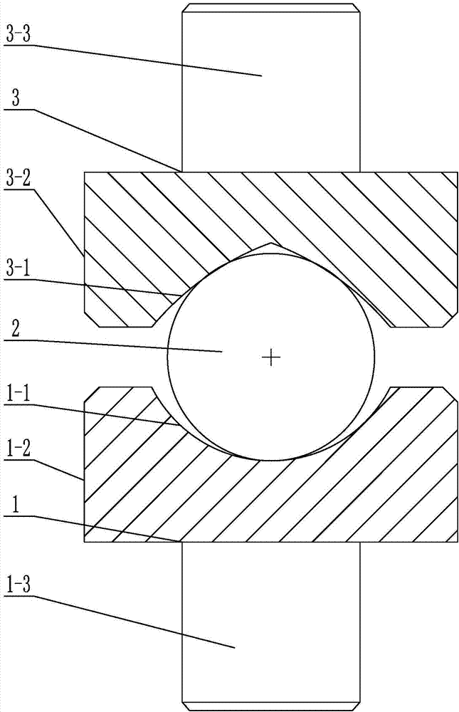
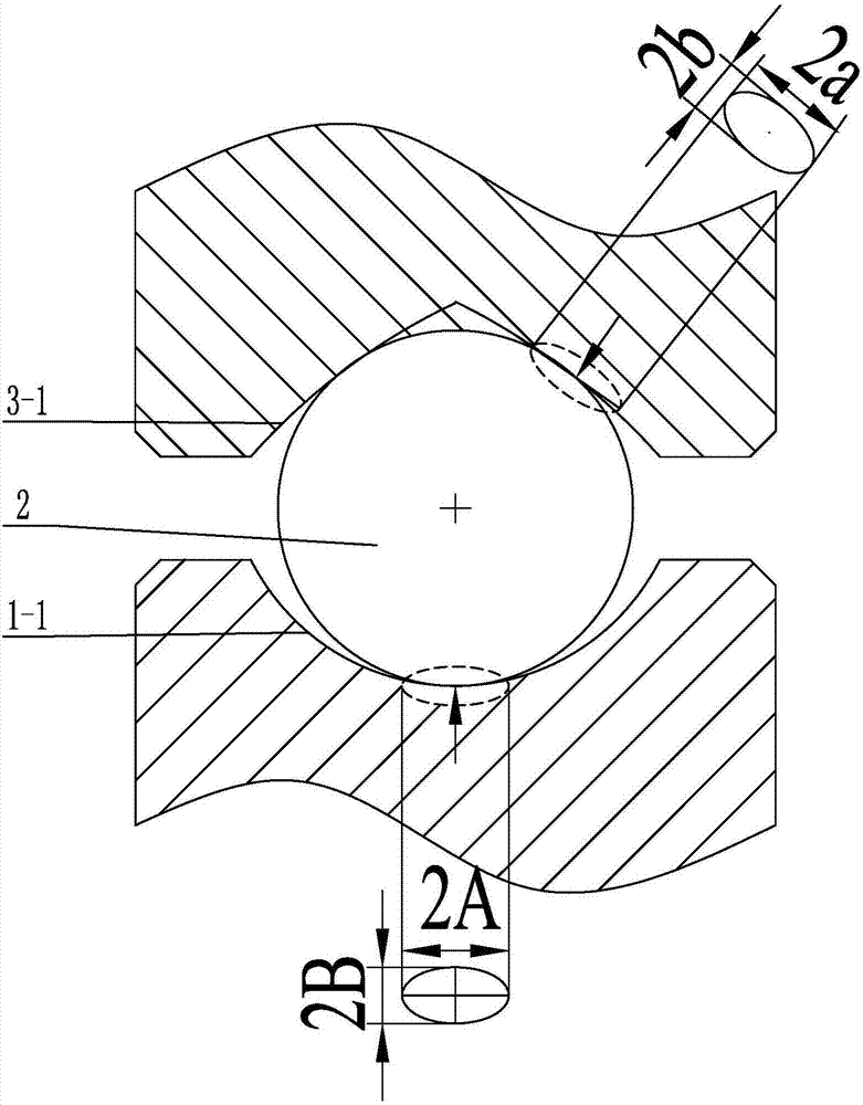
[0023] Specific implementation mode one: combine Figure 1 to Figure 2 To illustrate this embodiment, a Gothic groove support device in a center of mass measurement device described in this embodiment includes a lower support body 1, a sphere 2 and an upper support body 3, and the lower support body 1, a sphere 2 and an upper support body 3 Arranged sequentially from bottom to top, the middle part of the upper end surface of the lower support body 1 is provided with a spherical groove 1-1, the middle part of the lower end surface of the upper support body 3 is provided with a groove 3-1 along the horizontal direction, and the groove bottom of the groove 3-1 It is a tip, and the groove walls on both sides of the groove 3-1 are arc-shaped, and the ball 2 is arranged between the spherical groove 1-1 and the groove 3-1.

[0024] In this support mode, the lower support body 1 is fixed on the load cell, the upper support body 3 is fixed on the product bracket, the ball 2 can be auto...

specific Embodiment approach 2

[0028] Specific implementation mode two: combination figure 1 To describe this embodiment, the radius of curvature of the arc-shaped sidewall of the groove 3 - 1 in this embodiment is greater than the radius of curvature of the outer surface of the sphere 2 . Other compositions and connection methods are the same as those in Embodiment 1.

[0029] Such design ensures that the ball 2 can roll in the groove 3-1 along the axial direction of the groove 3-1.

specific Embodiment approach 3

[0030] Specific implementation mode three: combination figure 1 Describe this embodiment, the upper end of the lower support body 1 described in this embodiment is a first cylinder 1-2, the spherical groove 1-1 is arranged in the middle of the upper end surface of the first cylinder 1-2, and the upper end of the upper support body 3 The lower end is the second cylinder 3-2, and the groove 3-1 is arranged on the lower end surface of the second cylinder 3-2 along the radial direction. Other compositions and connection methods are the same as those in the second embodiment.

[0031] Such design makes the lower supporting body 1 form a ball-and-socket-shaped supporting body, and the upper supporting body 3 forms a supporting body with Gothic grooves.


PUM


Abstract

The invention relates to a Gothic groove supporting device of mass center measurement equipment, relates to the measurement technology field and solves a problem of influence on measurement accuracy caused by poor stability of a supporting device of mass center measurement equipment in the prior art. The Gothic groove supporting device comprises a lower supporting body, a ball body and an upper supporting board which are sequentially arranged from up to down, the middle portion of an upper end surface of the lower supporting body is provided with a spherical groove, the middle portion of a lower end surface of the upper supporting body is provided with a groove in the horizontal direction, the groove bottom of the groove is a tip end, two side groove walls of the groove are arc-shaped structures, and the ball body is arranged between the spherical groove and the groove. The Gothic groove supporting device is applicable to object mass center measurement.

Description

technical field [0001] The invention relates to the field of measurement technology, in particular to a Gothic groove support device in centroid measurement equipment. Background technique [0002] For the measurement of the center of mass of large-scale objects such as rockets, automobiles, and submarines, the existing measurement technology is mainly the static moment balance method, that is, three or four load cells are used to measure the weight of the product under test. ) The readings of the load cell and their relative positional relationship are used to calculate the position of the center of mass of the product to be tested. [0003] Among them, the three-point method is to install the product to be tested on the product bracket. The product bracket is supported by three load cells, and the three sensors are evenly distributed at 120 degrees. Through the measurement data of these three load cells and their geometric positional relationship, the center of mass of th...

Claims


Application Information

Patent Timeline
Patent Type & Authority Applications(China)
IPC IPC(8): G01M1/02
CPCG01M1/02
Inventor 张晓琳王梅宝于航唐文彦王军
Owner HARBIN INST OF TECH
Learn More