
oral cleaning device

An oral cleaning and cleaning device technology, applied in the field of oral cleaning, can solve the problems of manual or semi-automatic time-consuming and laborious, insufficient cleaning of teeth, gingival damage and bleeding, etc., and achieves improved effect, improved brushing effect, and good sealing effect.

Active Publication Date: 2018-07-27
刘平
View PDF6 Cites 0 Cited by
  • Summary
  • Abstract
  • Description
  • Claims
  • Application Information

AI Technical Summary

Problems solved by technology

[0002] When cleaning the oral cavity, the teeth are usually rinsed, and the rinse time is long, and the cleaning degree of the teeth by a single rinse method is not in place. Generally, the traditional brushing method uses a brush to clean the teeth. It is not advisable to use the horizontal brushing method, which may easily cause damage to the gums and bleeding, and the general manual or semi-automatic cleaning device is time-consuming and laborious

Method used


Image

  • oral cleaning device
  • oral cleaning device
  • oral cleaning device

Examples


Embodiment 1

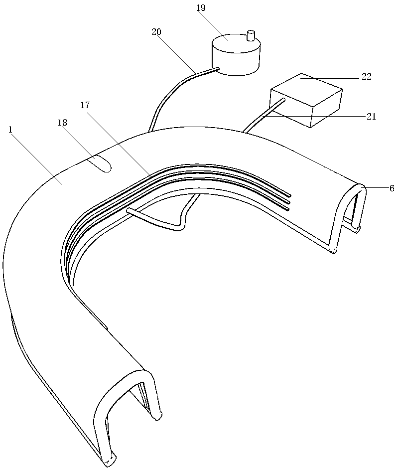
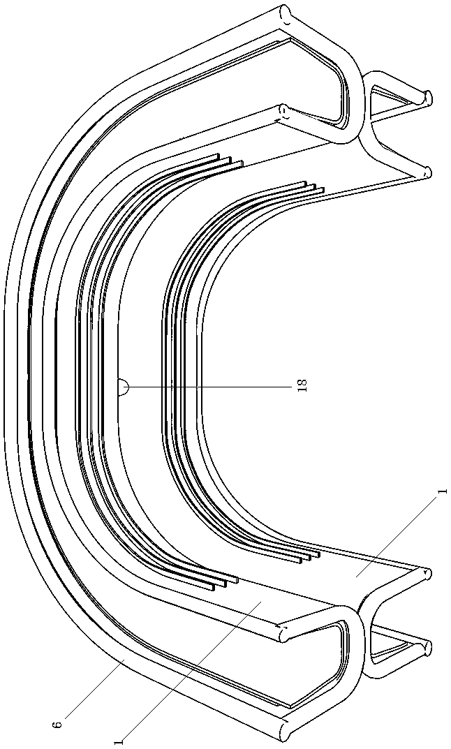
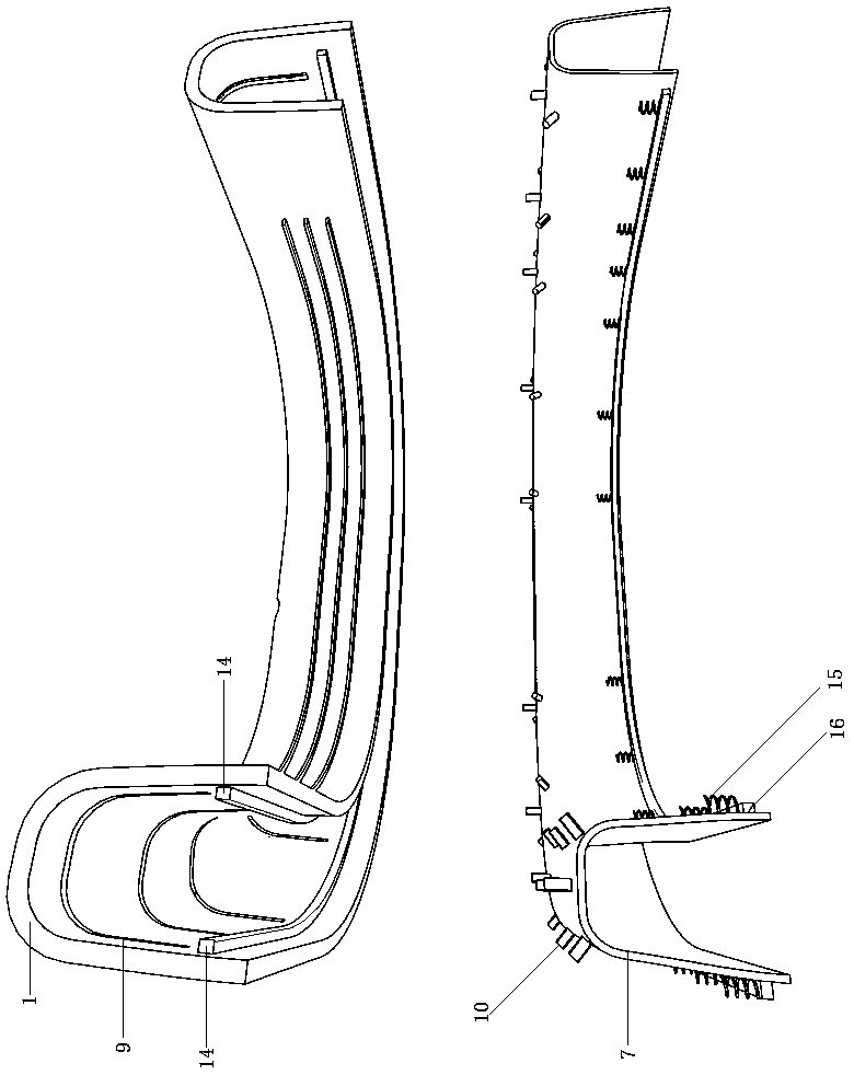
[0028] Embodiment one: if image 3 , 4 As shown, the motion cleaning device of this embodiment utilizes the vertical brush guide groove 9 to carry out the guiding motion, so as to realize the vertical brushing motion of the cleaning brush 8 driven by the installation film 7 . Open and control the electromagnetic drive device, when the electromagnetic strip 14 on the right is energized, it will generate magnetism, absorb the corresponding iron strip 16 below and move up, and compress the stage clip 15 in this side direction at the same time, at this time, the left electromagnetic strip 14 has no magnetism, and the left electromagnetic strip 14 has no magnetism. Under the action of the corresponding compression spring 15 below the electromagnetic strip 14 on the side, the iron bar 16 on the left side moves downward, and the iron bars 16 on both sides are fixedly connected with the lower parts on both sides of the installation film 7 respectively, and at this time, the right side...

Embodiment 2

[0029] Embodiment two: if Figure 5 , 6 As shown, the motion cleaning device in the present embodiment utilizes the arc-shaped mixing brush guide groove 13 to carry out the guiding movement, and realizes that the toothbrush base 11 drives the vertical and horizontal brushing movements of the cleaning brush 8, and the electromagnetic drive device in the present embodiment The energization control method can be the same as the energization control method in Embodiment 1, or the two groups of electromagnetic strips 14 can be synchronously powered on and off. Both power supply control methods generate forces in the up and down directions for driving the movement of the cleaning device. When the electromagnetic bar 14 drives the iron bar 16 to move up, the iron bar 16 is fixedly connected with the toothbrush base 11, and then drives the toothbrush base 11 to move upwards, and the toothbrush base 11 is guided by the arc-shaped mixed brush guide groove 13. At the same time, lateral ...


PUM


Abstract

The invention discloses an oral cleaning device and relates to the technical field of oral cleaning. The oral cleaning device comprises a tooth flushing device and a tooth occlusion sleeve matched with the tooth flushing device; a movable cleaning device is fitly arranged in the tooth occlusion sleeve; an electromagnetic driver is mounted at the lower portion of each of guide face A and guide face B; the movable cleaning device comprises a mounting film matched with the inside of the tooth occlusion sleeve; each of the guide face A and guide face B is evenly provide with vertical brush guide grooves in a vertical direction; the movable cleaning device alternatively comprises a toothbrush base matched with the tooth occlusion sleeve; each of the guide face A and guide face B is evenly provided with arc mixed brush guide grooves; each electromagnetic driver includes two electromagnet sets; a plurality of pressure springs are evenly connected to the electromagnetic adsorbing ends of the electromagnets; a steel bar is fixedly connected to the other end of each pressure spring. The oral cleaning device is simple in structure and convenient to use, can provide comprehensive efficient cleaning for teeth, has good cleaning effect and takes less time and labor.

Description

technical field [0001] The invention relates to the technical field of oral cavity cleaning. Background technique [0002] When cleaning the oral cavity, the teeth are usually rinsed, and the rinse time is long, and the cleaning degree of the teeth by a single rinse method is not in place. Generally, the traditional brushing method uses a brush to clean the teeth. It is not suitable to use the horizontal brushing method, which may easily cause damage and bleeding of the gums, and the general manual or semi-automatic cleaning device is time-consuming and laborious. Contents of the invention [0003] The technical problem to be solved by the present invention is to provide an oral cleaning device in view of the above-mentioned technical deficiencies. The structure is simple, the use is convenient, the teeth can be cleaned comprehensively and efficiently, the cleaning effect is good, and time and effort are saved. [0004] The technical solution adopted by the present inven...

Claims


Application Information

Patent Timeline
Patent Type & Authority Patents(China)
IPC IPC(8): A61C17/02A61B17/24
CPCA61B17/244A61C17/02
Inventor 刘平
Owner 刘平
Learn More