
Applied to the cutting station of thin plate cutting and forming machine and a kind of thin plate cutting and forming machine

A forming machine and thin plate technology, applied in the direction of manufacturing tools, metal processing, metal processing equipment, etc., can solve the problems of saw blade breakage, low degree of automation, and automatic control, so as to save human resources, improve cutting quality, and maintain stability Effect

Active Publication Date: 2018-12-07
山东磊信建设集团有限公司
View PDF8 Cites 0 Cited by
  • Summary
  • Abstract
  • Description
  • Claims
  • Application Information

AI Technical Summary

Problems solved by technology

[0003] For the cutting of thin plates, most of the existing technologies adopt some problems that the degree of automation is low and automatic control cannot be realized, and it is impossible to realize precise automatic control in terms of cutting thickness and process.
In addition, in the prior art solutions, it is difficult for the thickness of the finished sheet to be less than 3mm, and there are also big problems in the cutting accuracy and flatness
Furthermore, in the scheme of the prior art, since the tension pressure of the cutting saw blade cannot be effectively controlled within a stable range, but when the texture of the thin plate is uneven, or other possible operating fluctuations occur, the pressure of the saw blade load will suddenly Increase, the cutting pressure of the saw blade will suddenly increase and decrease, and even the sudden situation of saw blade breakage will occur, which will not only seriously affect the cutting quality of the thin plate and the service life of the saw blade, but also may cause safety accidents due to saw blade breakage

Method used


Image

  • Applied to the cutting station of thin plate cutting and forming machine and a kind of thin plate cutting and forming machine
  • Applied to the cutting station of thin plate cutting and forming machine and a kind of thin plate cutting and forming machine
  • Applied to the cutting station of thin plate cutting and forming machine and a kind of thin plate cutting and forming machine

Examples


Embodiment Construction

[0038] The technical scheme of the present invention will be further described below in conjunction with the accompanying drawings of the description:

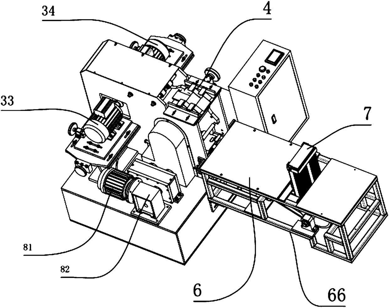
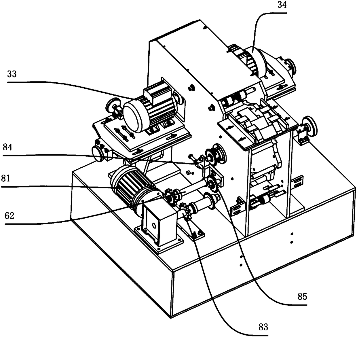
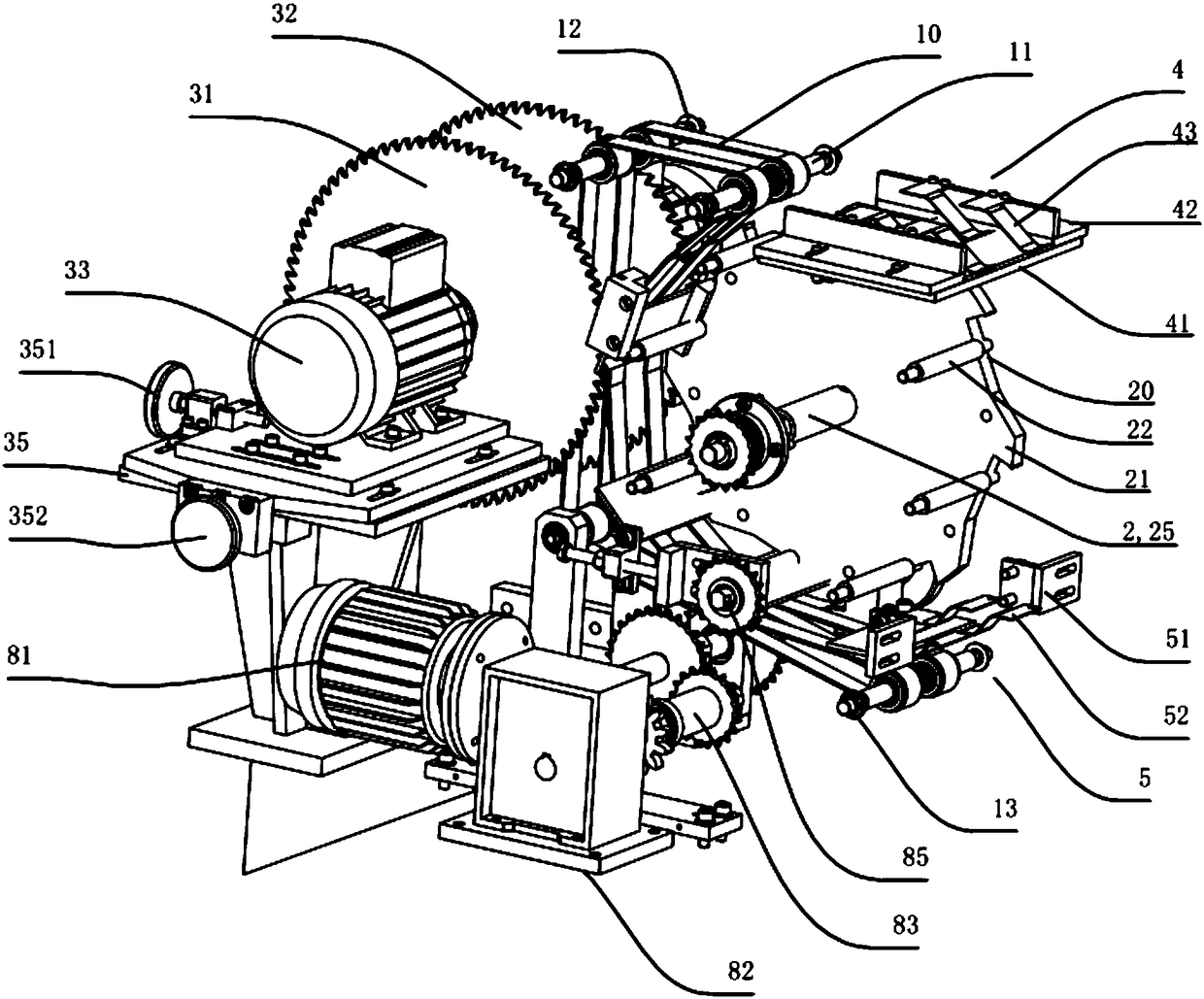
[0039] Such as Figure 1~8 As shown, the present invention proposes a specific embodiment of a thin plate cutting and forming machine, including a conveying station for conveying a thin plate and a finished thin plate obtained after cutting, and a cutting station for cutting a thin plate, wherein: the present invention A cutting station applied to a thin plate cutting and forming machine is provided, the cutting station includes a thin plate processing gear 2 for clamping a thin plate and a thin plate cutting device for cutting the thin plate clamped by the thin plate processing gear 2 Device 3, the conveying station includes a plate feeding device 4 for conveying the sheet to be cut into the cutting station, a sheet conveying device 1 for cooperating with the sheet cutting station, and a sheet conveying device 1 for feeding t...


PUM


Abstract

The invention provides a cutting station for a sheet cutting and forming machine and the sheet cutting and forming machine. The cutting station for the sheet cutting and forming machine comprises a sheet machining gear for clamping a sheet and a sheet cutting device for cutting the sheet clamped by the sheet machining gear. A plurality of tooth ports are formed in the edge of the sheet machining gear at equal intervals. A tooth slot is formed between every two adjacent tooth ports. Each tooth slot is provided with a sheet cutting fixing base used for receiving the sheet and delivering the sheet in a clamping mode. Each sheet cutting fixing base comprises a sheet storage roll for jacking the sheet from inside to outside, a lower sheet cutting fixing supporting seat connected to one end of the sheet storage roll, and an upper sheet cutting fixing supporting seat connected to the other end of the sheet storage roll. Thus, the sheet cutting quality and the equipment operation safety are greatly improved, the rejection rate is decreased, the whole cutting and forming machine can be effectively and automatically controlled, and the manpower resource is saved.

Description

technical field [0001] The invention relates to the technical field of thin plate cutting equipment, in particular to a cutting station applied to a thin plate cutting and forming machine and a thin plate cutting and forming machine. Background technique [0002] As an important building and decoration material, sheet metal production and processing directly affect the aesthetic feeling and decoration effect of buildings. Most of the thin plates need to be processed before they can be used as construction and decoration materials. Therefore, with the continuous improvement of people's pursuit of building aesthetics and safety, the thin plate processing industry has shown a huge market prospect, and the most important in thin plate processing It is two aspects of technology and equipment. Among them, for thin plate processing equipment, the main research direction of the industry is also concentrated in the fields of thin plate cutting, grinding, splicing, beautification and...

Claims


Application Information

Patent Timeline
Patent Type & Authority Patents(China)
IPC IPC(8): B23D47/04
CPCB23D47/04B23Q7/00B23Q7/05
Inventor 柏伟伟
Owner 山东磊信建设集团有限公司
Learn More