Movable telegraph pole which is based on control of pneumatic motor and used for easily collapsing ground

A technology for air motors and utility poles, applied in the field of utility poles, can solve the problems that the wires are easily broken, the function is single, and the wires cannot continue to transmit electric energy.

Active Publication Date: 2017-11-21
重庆山渝道科技有限公司
View PDF5 Cites 0 Cited by
  • Summary
  • Abstract
  • Description
  • Claims
  • Application Information

AI Technical Summary

Problems solved by technology

[0002] At present, the existing electric poles have simple structure and single function; when the ground on which the electric poles are fixed collapses, the electric poles will move under the action of gravity, and the moving electric poles will pull the electric wires to move together. It is fixed by the support rod, and at this time the wire in the middle will pull the wire down, and the wire under the downward force is easily broken, or the support rod that fixes the wire is pulled to the end, and the wire at this time will not be able to continue to transmit electric energy , so it is necessary to design a mobile utility pole based on air motor control for easy-to-collapse ground

Method used


Image

  • Movable telegraph pole which is based on control of pneumatic motor and used for easily collapsing ground
  • Movable telegraph pole which is based on control of pneumatic motor and used for easily collapsing ground
  • Movable telegraph pole which is based on control of pneumatic motor and used for easily collapsing ground

Examples


Embodiment Construction

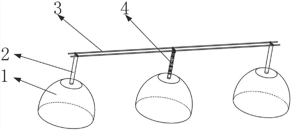
[0045] Such as figure 1 As shown, it includes utility pole mechanism 4, moving mechanism 5, such as figure 1 As shown, two of the support rods 2 are respectively installed on the top of two hillsides 1; as figure 1 As shown, two electric wires 3 are installed on the tops of two support rods 2; the utility pole mechanism 4 is installed on the top of the hillside 1 between the two support rods 2; as figure 1 , 4 , 5, the moving mechanism 5 is installed on the utility pole mechanism 4 upper side, and the moving mechanism 5 cooperates with two electric wires 3 .

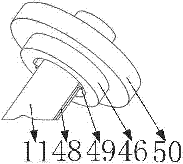
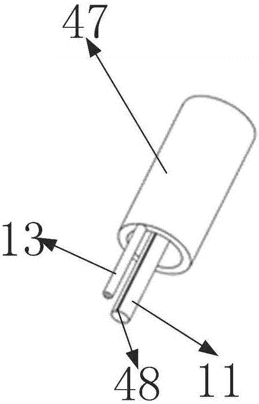
[0046] Such as Figure 5 , 7 As shown, the utility pole mechanism 4 includes a support block 10, an air chamber 57, a T-shaped groove 39, a positioning groove 56, a guide column 11, a first weight 12, a driving wheel 58, a driving gear 13, and a first utility pole shell 14 , the support cylinder 15, the second weight 16, the locking mechanism 17, the support ring 55, the second wire rod shell 18, the third weight 19...


PUM


Abstract

The invention belongs to the technical field of telegraph poles, and particularly relates to a movable telegraph pole which is based on the control of a pneumatic motor and used for the easily collapsing ground. The movable telegraph pole includes a telegraph mechanism and a movable mechanism, and two support rods are mounted on the tops of two mountain slopes respectively and play a role of supporting wires; the two wires are mounted at the top ends of the support rods and play a role of transmitting electric energy; one the one hand, the telegraph pole mechanism is mounted at a mountain slope between the two support rods and plays a role of supporting the wires; on the other hand, when the mountain slope where the telegraph pole mechanism is located collapses, the telegraph pole mechanism can drive the movable mechanism to move, and the movable mechanism can drive the telegraph pole mechanism to move a position which does not collapse and make the telegraph pole mechanism deeply inserted into the ground, so that the telegraph pole mechanism plays the role of supporting the wires again; the movable mechanism is mounted at the upper side of the telegraph pole mechanism, and the effect of the cooperation of the movable mechanism and the two wires is driving the telegraph pole mechanism to move and support the wires.

Description

Technical field [0001] The invention belongs to the technical field of utility poles, and in particular relates to a mobile utility pole used on ground prone to subsidence controlled by an air motor. Background technique [0002] At present, the existing electric poles have simple structure and single function; when the ground on which the electric poles are fixed collapses, the electric poles will move under the action of gravity, and the moving electric poles will pull the electric wires to move together. It is fixed by the support rod, and at this time the wire in the middle will pull the wire down, and the wire under the downward force is easily broken, or the support rod that fixes the wire is pulled to the end, and the wire at this time will not be able to continue to transmit electric energy , so it is necessary to design a mobile utility pole based on air motor control for easy-to-collapse ground. [0003] The present invention designs a mobile utility pole used on ...

Claims


Application Information

Patent Timeline
Patent Type & Authority Applications(China)
IPC IPC(8): E04H12/18E04H12/24
CPCE04H12/18E04H12/24
Inventor 袁永
Owner 重庆山渝道科技有限公司
Why Eureka
Try Eureka