Multi-rotor motor or generator

A motor and generator technology, applied in the direction of electric components, electrical components, electromechanical devices, etc., can solve the problems of narrow motor or generator range, low power density ratio, low transmission torque, etc., and achieve efficient working range and power density. The effect of high ratio and large torque transmission

Inactive Publication Date: 2017-11-21
汤斌
View PDF0 Cites 0 Cited by
  • Summary
  • Abstract
  • Description
  • Claims
  • Application Information

AI Technical Summary

Problems solved by technology

[0002] Existing motors or generators are mainly composed of a stator and a rotor. The rotor windings or the stator windings are energized to generate a magnetic field. The rotor and the stator rotate under the interaction force of their respective magnetic fields, thereby converting electrical energy into mechanical energy or mechanical energy into electrical energy. The magnetic poles of the motor and motor of this structure are respectively arranged on the stator and the rotor, and the interacting magnetic poles mainly overlap in the radial direction of the rotor, so that the torque of the magnetic field force of the interacting magnetic poles (windings) is relatively small, so that the motor or The generator is in a high-efficiency working range, the range is narrow, the transmission torque is low, the power density ratio is low, and the volume is large

Method used


Image

  • Multi-rotor motor or generator
  • Multi-rotor motor or generator
  • Multi-rotor motor or generator

Examples


specific Embodiment approach

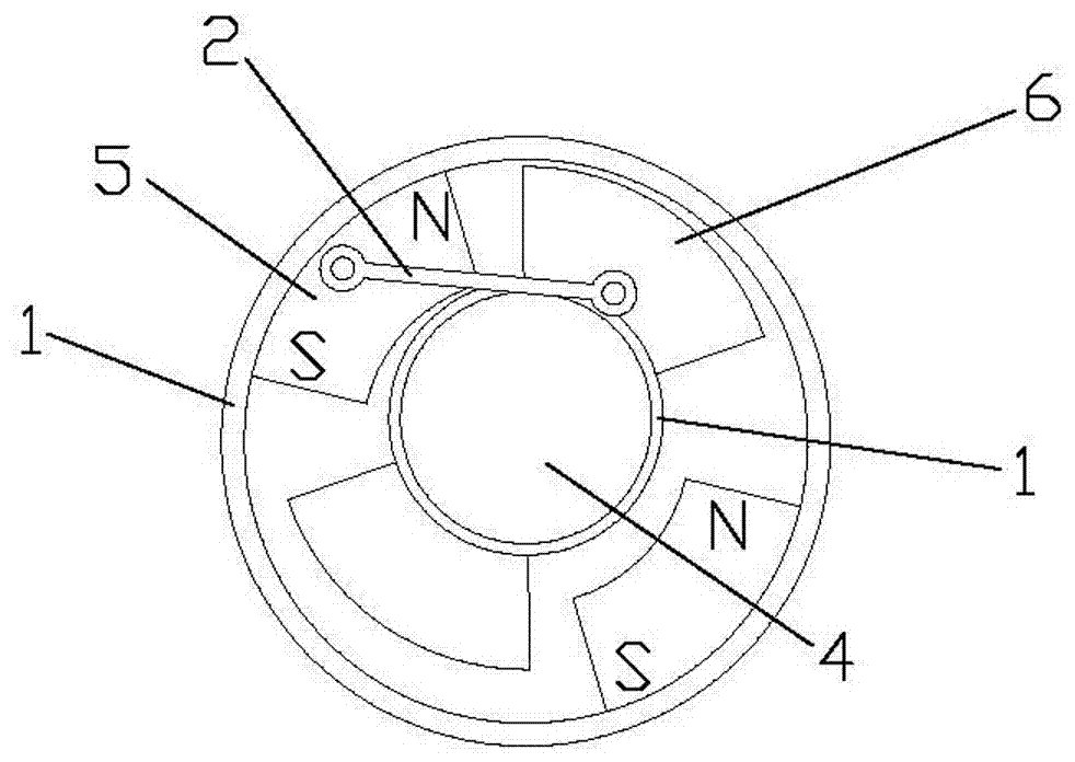
[0028] to combine figure 1 , The multi-rotor motor or generator includes a first rotor 1, a connecting rod 2, a second rotor 3, and an eccentric member 4; the eccentric member 4 is arranged on the frame, and the first rotor 1 is rotatably arranged on the machine frame On the frame, one end of the connecting rod 2 is rotatably arranged on the first rotor 1, the other end of the connecting rod 2 is rotatably arranged on the second rotor 3, and the second rotor 3 is rotatably arranged on the eccentric member 4. The eccentric 4 is not concentrically arranged with the first rotor 1 . In this embodiment, one first rotor 1 and one second rotor 3 are provided, a pair of first rotor magnetic poles 5 are arranged radially on the inner wall of the first rotor 1, and a pair of second rotor poles 5 are arranged radially on the outer wall of the second rotor. Two rotor poles 6. The first rotor poles 5 form a pair of N poles and S poles in the circumferential direction of the first rotor 1...

Embodiment approach

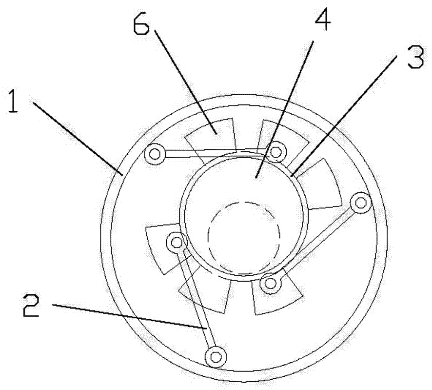
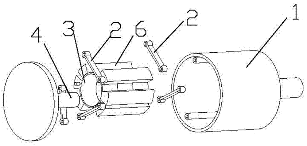
[0031] figure 2 It is a schematic plan view of the second rotor 3 of the present invention when there are three, image 3 yes figure 2 The schematic diagram of the decomposition structure of the shown embodiment, Figure 4 yes image 3 Schematic diagram of the assembled appearance structure, Figure 5 yes Figure 4 The A-A cross-sectional structure schematic diagram of Figure 6 yes figure 2 Schematic diagram of the internal rotor assembly structure.

[0032] figure 2 There are three connecting rods 2 in one-to-one correspondence with the three second rotors 3, and one end of the three connecting rods 2 is rotatably connected to the shaft / shaft hole evenly distributed on the inner wall of the first rotor 1, and the three connecting rods The other end of 2 is rotatably connected to the shafts / shaft holes distributed on the outer walls of the three second rotors 3 respectively, the three second rotors 3 are connected in series on the eccentric member 4, and the three...


PUM


Abstract

A multi-rotor motor or generator, including a first rotor, a connecting rod, a second rotor, and an eccentric member, the eccentric member is arranged on a frame, the first rotor is rotatably arranged on the frame, and the connecting rod One end of the connecting rod is rotatably set on the first rotor, the other end of the connecting rod is rotatably set on the second rotor, the second rotor is rotatably set on the eccentric member, and a magnetic pole is set on the second rotor . The multi-rotor motor or generator of the present invention relates to the field of motor or generator equipment, and is different from the existing motor or generator in which the magnetic poles are respectively arranged on the stator and the rotor. The magnetic poles of the present invention are all arranged on the rotor. The present invention The advantages of the motor or generator are light weight, small size, wide range of high-efficiency working range, high electromechanical conversion efficiency, and large power density ratio.

Description

technical field [0001] The invention relates to the field of motors or generators, in particular to a multi-rotor motor or generator in which magnetic poles are arranged on rotors. Background technique [0002] Existing motors or generators are mainly composed of a stator and a rotor. The rotor windings or the stator windings are energized to generate a magnetic field. The rotor and the stator rotate under the interaction force of their respective magnetic fields, thereby converting electrical energy into mechanical energy or mechanical energy into electrical energy. The magnetic poles of the motor and motor of this structure are respectively arranged on the stator and the rotor, and the interacting magnetic poles mainly overlap in the radial direction of the rotor, so that the torque of the magnetic field force of the interacting magnetic poles (windings) is relatively small, so that the motor or The generator is in a narrow high-efficiency working range, low transmission t...

Claims


Application Information

Patent Timeline
Patent Type & Authority Applications(China)
IPC IPC(8): H02K16/02H02K7/075
CPCH02K16/02H02K7/075
Inventor 汤斌
Owner 汤斌
Why Eureka
Try Eureka