Eureka AIR delivers breakthrough ideas for toughest innovation challenges, trusted by R&D personnel around the world.

Independent dining device for critical patient

A patient and critically ill technology, applied in the field of self-catering devices for critically ill patients, can solve problems such as low efficiency, inconvenient family life for critically ill patients, and restrictions on self-care ability of critically ill patients

Inactive Publication Date: 2017-11-24
龙文庆
View PDF0 Cites 2 Cited by
  • Summary
  • Abstract
  • Description
  • Claims
  • Application Information

AI Technical Summary

Problems solved by technology

[0002] At present, for people with hand disabilities, the diet is mainly fed by others, which severely limits the self-care ability of critically ill patients, and at the same time brings inconvenience to the family life of severe patients; in response to this problem, some auxiliary eating devices for critically ill patients have appeared, to a certain extent The self-care of critically ill patients has been realized and the self-confidence of critically ill patients has been improved. These devices are mainly divided into two types, one is feeding by manipulators controlled by human feet, and the other is feeding by rotating tables combined with push plates; these two devices are respectively They have their own shortcomings. The former uses human feet to control the manipulator to take food, which is complicated to operate, low in efficiency, and high in equipment cost; the latter can only meet the push feeding of dishes or staple foods, and cannot satisfy liquid food, dishes, and staple foods at the same time. , and the rotating dining table occupies a large area and is poor in portability, so it is not suitable for occasions with small spaces such as hospitals

Method used


Image

  • Independent dining device for critical patient
  • Independent dining device for critical patient
  • Independent dining device for critical patient

Examples


specific Embodiment approach 1

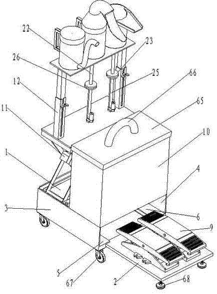
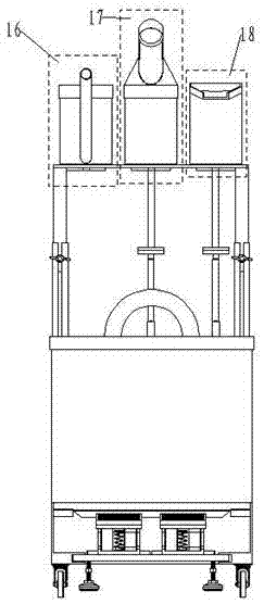
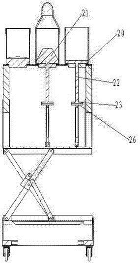
[0033] Embodiment 1: Combining Figure 1-10 As shown in the figure, an autonomous dining device for critically ill patients includes a backboard 1 and a slide plate 2. The left side plate 3 is welded to the front left end of the backboard 1, the right side plate 4 is welded to the right end of the front surface of the backboard 1, and the left side plate 3 and the right side plate 4 are both perpendicular to the back plate 1; the bottom of the right side 4 of the left side plate 3 is welded with a left bottom plate 5, and the left bottom plate 5 is perpendicular to the left side plate 3; the bottom of the left side of the right side plate 4 is welded with a right Bottom plate 6, right bottom plate 6 and right side plate 4 are vertical; the back of left bottom plate 5 and right bottom plate 6 are welded firmly with the front of back plate 1; The left bottom plate 5; the front left end of the right bottom plate 6 is provided with a right guide groove 8, and the right guide groov...


PUM


Abstract

The invention relates to the technical field of medical devices, in particular to a self-eating device for the disabled. Two-way foot switches are fixedly installed on the left side and right side of the top surface of the sliding board, and the disabled can realize the two-way foot switch by stepping on the two-way foot switch with both feet. Control of food supply: the liquid food container is installed on the left installation hole, the dish container is installed on the middle installation hole, and the staple food container is installed on the right installation hole, so that the disabled can eat a variety of foods independently; The front end of the top surface of the board and the right side board is fixedly equipped with a storage box. When the device is not in use, the liquid food container, dish container and staple food container can be placed in the storage box, and the slide plate is slid into the back board and the left side board. In the groove formed with the right side plate, lower the lift to the lowest position, adjust the telescopic rod to the shortest, the equipment occupies a small volume, is suitable for a wide range of occasions, and is easy to carry, which is of great help to the disabled to improve their confidence in life.

Description

technical field [0001] The invention relates to the technical field of medical devices, in particular to an autonomous dining device for critically ill patients. Background technique [0002] At present, for people with handicapped hands, the diet is mainly fed by others, which seriously limits the self-care ability of critically ill patients and brings inconvenience to the family life of critically ill patients. In response to this problem, some assisted dining devices for critically ill patients have emerged, which to a certain extent These devices are mainly divided into two types, one is for feeding by manipulators controlled by human feet, and the other is for feeding by rotating dining table combined with push plate; these two devices are respectively It has its own shortcomings. The former uses human feet to control the manipulator to take food, which is complicated in operation, low in efficiency, and expensive in equipment; the latter can only meet the push feeding ...

Claims


Application Information

Patent Timeline
IPC IPC(8): A61G12/00A61J9/04A61J15/00
CPCA61G12/00A61J9/04A61J15/0011A61J15/0026
Inventor 龙文庆
Owner 龙文庆
Why Eureka
Eureka Blog
Learn More