Extruding roller level difference control device and method

A control device and roller technology, which is applied in the field of squeeze roller level difference control device, can solve the problems of abandoned plates and waste, and achieve the effects of energy saving, easy operation and simple structure

Pending Publication Date: 2017-11-24
SHANDONG XINHEYUAN HEAT TRANSFERRING TECH
View PDF6 Cites 6 Cited by
  • Summary
  • Abstract
  • Description
  • Claims
  • Application Information

AI Technical Summary

Problems solved by technology

[0004] The technical task of the present invention is to address the above deficiencies and provide a squeeze roller di...

Method used


Image

  • Extruding roller level difference control device and method
  • Extruding roller level difference control device and method
  • Extruding roller level difference control device and method

Examples


Embodiment 1

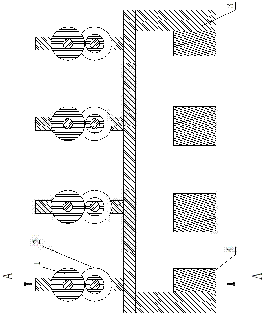
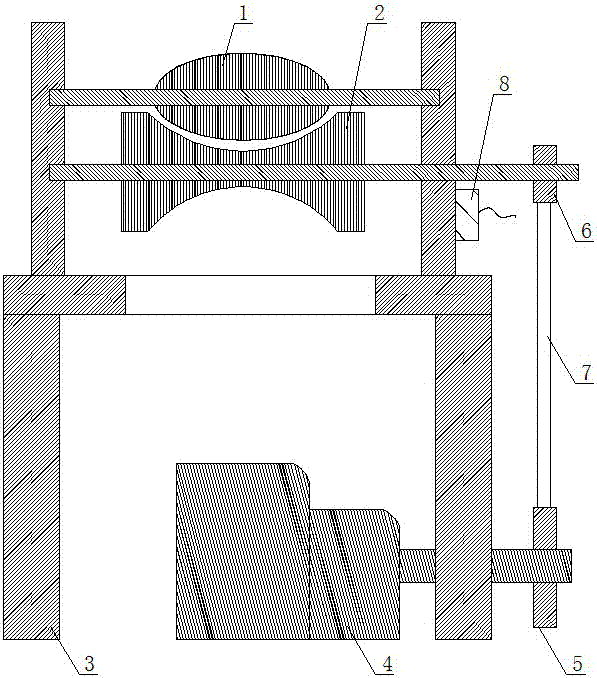
[0023] as attached figure 1 , attached figure 2 And attached image 3 As shown, the extrusion roller differential control device includes a frame 3, an extrusion roller and a driving device, and the extrusion roller includes a concave wheel 2 and a cam 1 which are arranged up and down oppositely, and the cam 1 is located above the concave wheel 2, and the concave wheel 2 There is a gap between the wheel 2 and the cam 1 for the plate to pass through, and the cam 1 and the concave wheel 2 cooperate to squeeze the plate, and the driving device is connected with the extrusion roller and drives the concave wheel 2 and the cam 1 to rotate synchronously in different directions; the above There are a plurality of extrusion rollers and driving devices. The plurality of extrusion rollers are arranged on the frame 3 and arranged in sequence along the conveying direction of the plate to form a forming mechanism. Each extrusion roller corresponds to a driving device, and each driving Th...

Embodiment 2

[0028] In the extrusion roller differential control method of the present invention, the plate is bent through the extrusion roller differential control device disclosed in Embodiment 1, and the rotational speeds of the multiple extrusion rollers in the forming mechanism are set to be along the conveying direction Incrementing successively to form a differential control forming mechanism, through which the plate is bent and deformed step by step to obtain a coiled tube. Including the following steps:

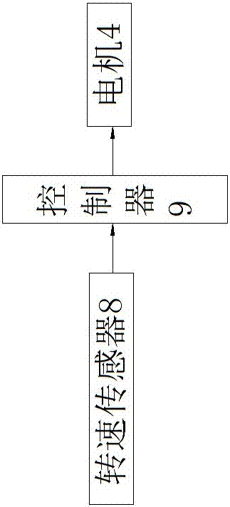
[0029] (1) Set the rotation speed of the extrusion rollers through the driving device, so that the concave wheel 2 and the cam 1 in each extrusion roller rotate in different directions synchronously, and make all the extrusion rollers in the forming mechanism meet the following conditions: The rotation speed of each extrusion roller increases sequentially along the conveying direction of the plate, forming a differential control forming mechanism;

[0030] (2) Send the flat pla...


PUM


Abstract

The invention discloses an extruding roller level difference control device and method, belongs to the field of reel pipe manufacturing devices and aims to solve the technical problem that tail ends of plates are abandoned to cause plate waste. The extruding roller level difference control device structurally comprises a rack, multiple extruding rollers and multiple driving devices, wherein the extruding rollers comprise concave wheels and convex wheels which are arranged oppositely, a gap for plates to pass through is formed between each concave wheel and the corresponding convex wheel, the driving devices are connected with the extruding rollers and drive the concave wheels and the convex wheels to synchronously rotate in different-direction mode, the multiple extruding rollers are arranged on the rack and are sequentially arranged in the conveying direction of the plates to form a forming mechanism, each driving device is connected with the corresponding concave wheel and the corresponding convex wheel and can drive the corresponding concave wheel and the corresponding convex wheel to synchronously rotate in different-direction mode, the rotation speeds of the multiple extruding rollers are progressively increased in the conveying direction of the plates, and each driving device is connected to a controller. By adopting the method, plates are coiled through the extruding roller level difference control device.

Description

technical field [0001] The invention relates to the field of roll tube preparation devices, in particular to a device and method for controlling the differential of extrusion rollers. Background technique [0002] In the production process of the pipe, the flat sheet is usually bent and formed by a pipe coiling machine. Extrusion rollers are usually used to extrude the sheet in the existing pipe coiling machine. The extrusion rollers are mainly composed of oppositely arranged Composed of concave wheel and cam, the flat plate is fed between the concave wheel and the cam, and the concave wheel and the cam cooperate to bend and deform the plate. During the bending process of the plate by means of extrusion rollers, the extrusion and bending of the tail end of the plate is often abandoned because it cannot be controlled, resulting in waste of the plate. [0003] How to realize the bending deformation of the whole plate and avoid the waste of the plate is a technical problem to ...

Claims


Application Information

Patent Timeline
IPC IPC(8): B21D5/12
CPCB21D5/12
Inventor 张洪延张志强
Owner SHANDONG XINHEYUAN HEAT TRANSFERRING TECH
Why Eureka
Try Eureka