Stamping device capable of automatically correcting stamping workpieces and working method of stamping device

A punching device and a technology for stamping workpieces, which are applied in the direction of feeding devices, positioning devices, storage devices, etc., can solve problems such as difficult to find and find problems, and achieve the effects of reasonable structural design, avoiding danger, and ensuring stamping accuracy

Inactive Publication Date: 2017-11-24
太仓市华天冲压五金制品厂
View PDF6 Cites 8 Cited by
  • Summary
  • Abstract
  • Description
  • Claims
  • Application Information

AI Technical Summary

Problems solved by technology

[0002] In the sheet metal parts production and processing industry, it is often necessary to perform stamping processing on sheet metal parts. Stamping processing uses the power of conventional or special stamping equipment to directly deform the sheet metal in the mold to obtain a certain shape. Compared with castings and forgings, stamping parts have the characteristics of thinness, uniformity, lightness and strength. Due to the use of precision molds, the precision of the workpiece can reach micron level, and the repeatability is high and the specifications are consistent. , can punch out certain shapes such as holes and bosses. The size of the stamped workpiece has a direct relationship with the quality of the stamping process. However, most stamping devices can only find out that the processed product is unqualified after the stamping of the workpiece is completed. When looking for problems It is more difficult, if the stamping misalignment caused by the offset of the workpiece is not easy to find

Method used


Image

  • Stamping device capable of automatically correcting stamping workpieces and working method of stamping device

Examples


Embodiment

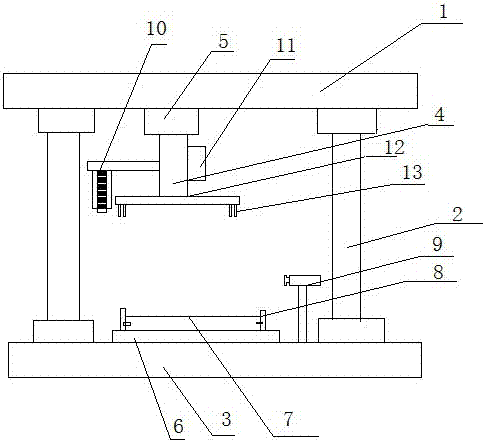
[0025] like figure 1 Shown is a stamping device and its working method for automatically correcting stamping workpieces. The stamping device includes an upper die base 1, a guide column 2, a lower die base 3, a punch 4, a punch holder 5, a punching table 6, a forming Mold 7, mold locking device 8, product calibration device 9, monitoring component 10 and monitoring terminal 11, the upper mold base 1 and the lower mold base 3 are connected by guide columns 2, and the punch 4 is fixed by the punch The base 5 is set on the upper mold base 1, the monitoring component 10 is set on the punch fixing base 5, the monitoring component 10 is electrically connected to the monitoring terminal, the punching table 6 is set on the lower mold base 3, and the forming mold 7 passes through the mold lock The tightening device 8 is fixed on the stamping workbench 6, and the product correction device 9 is arranged on the right side of the forming die 7; the forming die 7 is also provided with an in...


PUM


Abstract

The invention discloses a stamping device capable of automatically correcting stamping workpieces and working method of the stamping device. The stamping device comprises an upper die holder, a guide column, a lower die holder, a punch, a punch fixing seat, a stamping worktable, a forming die, a die locking device, a product correcting device, a monitoring component and a monitoring terminal, the upper die holder is connected with the lower die holder the through the guide column, the punch is arranged on the upper die holder through the punch fixing seat, the monitoring component is arranged on the punch fixing seat and electrically connected with the monitoring terminal, the stamping worktable is arranged on the lower die holder, the forming die is fixed on the stamping worktable through the die locking device, the product correcting device is arranged on the right side of the forming die, an in-place sensor is arranged on the forming die, a stamping control device is arranged on the punch, an output end of the in-place sensor is connected with the stamping control device, and the stamping control device controls the punch to rise, fall and stop. The stamping device is reasonable in structure design, stamping process can be monitored in real time, monitoring information is transmitted to the monitoring terminal and viewed through the monitoring terminal, stamping states do not need to be observed by standing in front of the stamping device, and the stamping device is convenient and practical.

Description

technical field [0001] The invention relates to the technical field of punching, in particular to a punching device for automatically correcting punched workpieces and a working method thereof. Background technique [0002] In the sheet metal parts production and processing industry, it is often necessary to perform stamping processing on sheet metal parts. Stamping processing uses the power of conventional or special stamping equipment to directly deform the sheet metal in the mold to obtain a certain shape. Compared with castings and forgings, stamping parts have the characteristics of thinness, uniformity, lightness and strength. Due to the use of precision molds, the precision of the workpiece can reach micron level, and the repeatability is high and the specifications are consistent. , can punch out certain shapes such as holes and bosses. The size of the stamped workpiece has a direct relationship with the quality of the stamping process. However, most stamping devices...

Claims


Application Information

Patent Timeline
IPC IPC(8): B21D43/00B21D22/02
CPCB21D22/02B21D43/003
Inventor 黄晓雷
Owner 太仓市华天冲压五金制品厂
Why Eureka
Try Eureka