
A manufacturing method and device for friction stir near net shape additive of composite materials

A friction stir, near-net-shape technology, used in manufacturing tools, metal processing equipment, welding equipment, etc., can solve the problems of high clamping requirements, long processing time, complicated disassembly and assembly, etc., to achieve high material utilization, increase growth rate. Material efficiency and simple device structure

Active Publication Date: 2019-06-11
NANCHANG HANGKONG UNIVERSITY
View PDF7 Cites 0 Cited by
  • Summary
  • Abstract
  • Description
  • Claims
  • Application Information

AI Technical Summary

Problems solved by technology

[0004] The purpose of the present invention is to provide a manufacturing method and device for friction stir near-net shape additive of composite materials, so as to solve the problem of high workpiece clamping requirements, complicated disassembly and assembly, and time-consuming follow-up processing in friction stir additive manufacturing in the prior art. Longer problem, the device of the present invention can realize near-net-shape additive manufacturing of composite materials in solid state, the device is simple, easy to operate, high material utilization rate, and has no defects such as pores produced by the melting method

Method used


Image

  • A manufacturing method and device for friction stir near net shape additive of composite materials
  • A manufacturing method and device for friction stir near net shape additive of composite materials
  • A manufacturing method and device for friction stir near net shape additive of composite materials

Examples


Embodiment 1

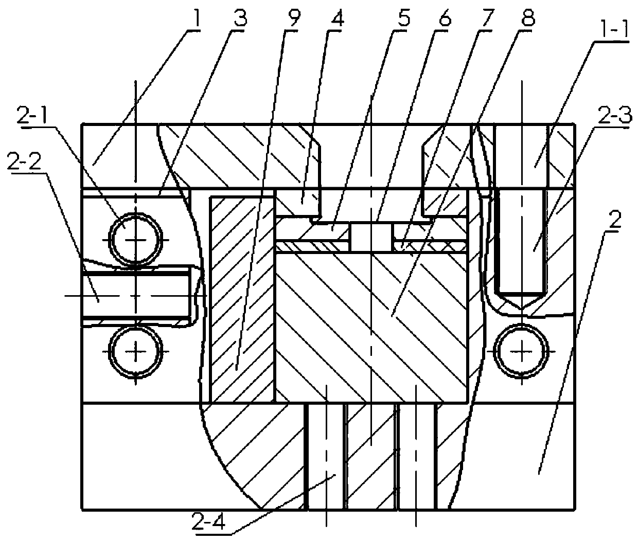
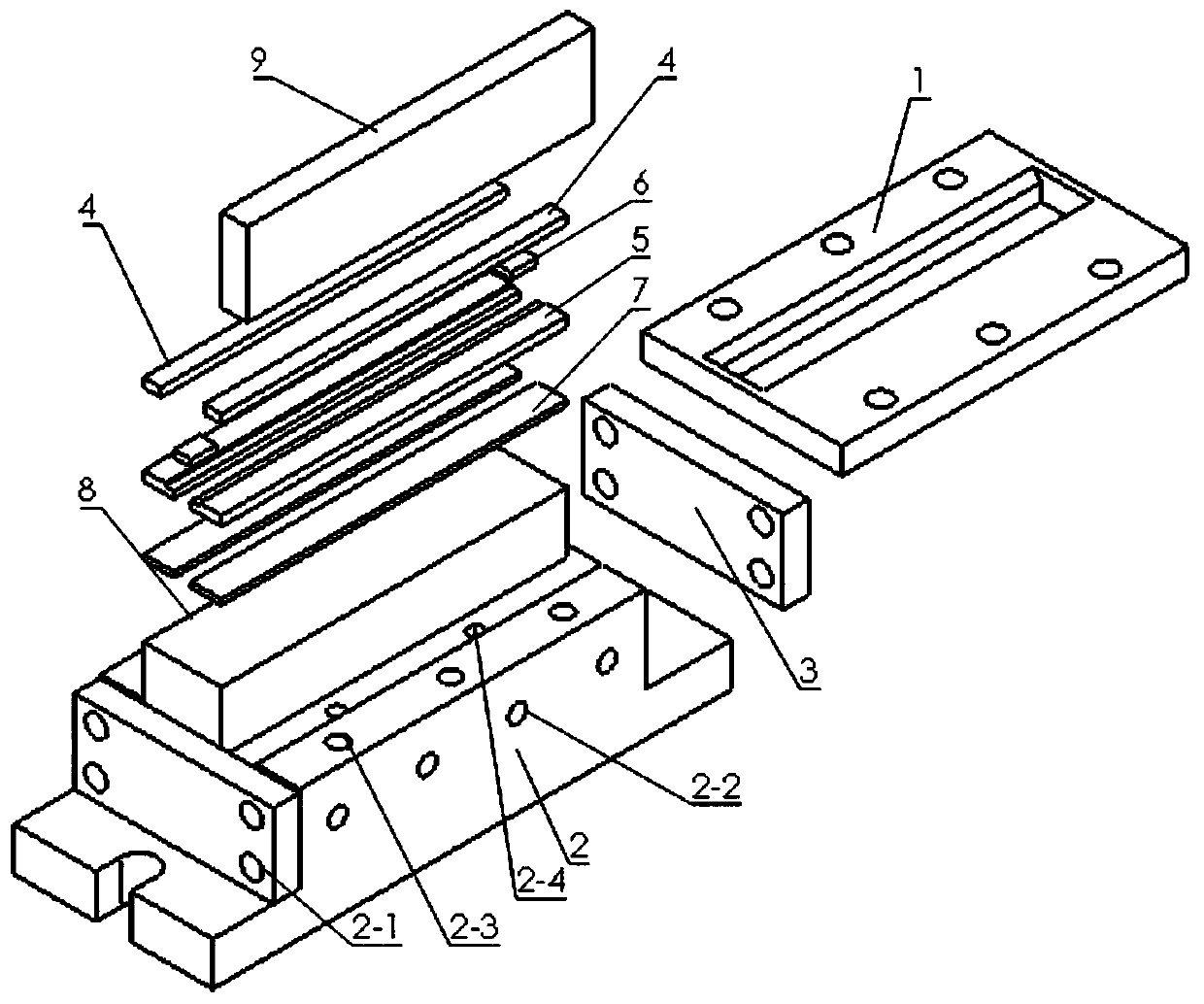
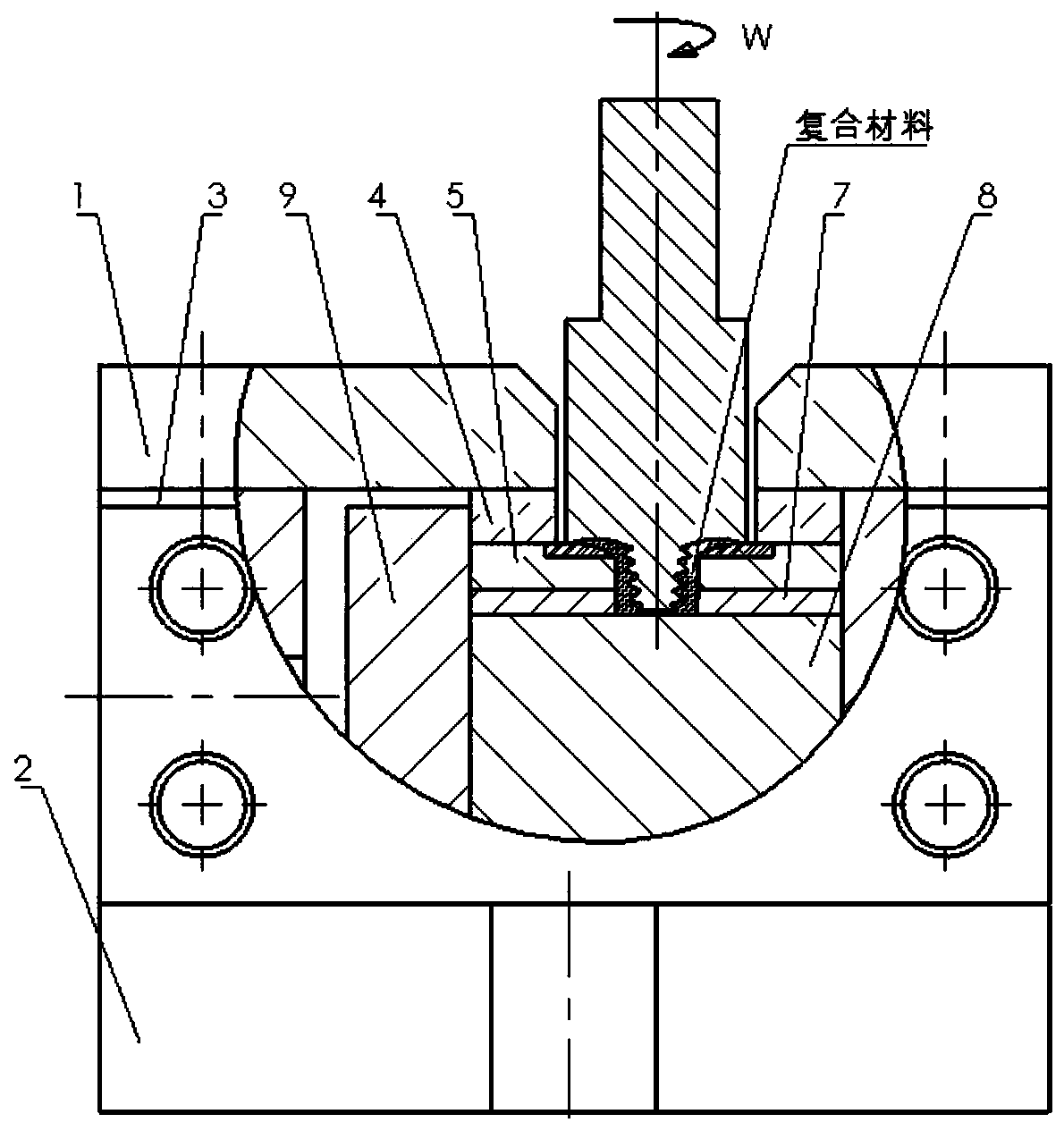
[0032] Such as Figure 1-3 As shown, this embodiment describes in detail a manufacturing method and device for friction stir near-net shape additive of composite materials according to the present invention.

[0033] Such as figure 1 and 2 As shown, this embodiment provides a device for friction stir near-net shape additive of composite materials, including a mold base 2, a cavity plate and a cover plate 1, and end stops are installed at both ends of the mold base 2 Plate 3, a pad 8 is placed in the cavity of the mold base 2, and the two ends of the pad 8 are against the end baffle 3, and the side of the pad 8 is equipped with a side baffle 9, and the side baffle 9 and the two A terminal baffle can better stabilize the cushion block 8. A cavity plate is arranged on the top of the cushion block 8. The cavity plate is arranged as a left and right split and a rectangular gap is reserved in the middle. The cover plate 1 is connected to the upper part of the mold base 2. There i...

Embodiment 2

[0045] Embodiment 2, in step 2, the width of the plug 6 is 9mm ± 0.01, the material thickness is 4mm, the rotation speed is 600rpm, the welding speed is 45mm / min, the inclination angle of the stirring head is 2°, and the stirring needle is stirred at least 5 times; other steps and embodiments same.

Embodiment 3

[0046] Embodiment 3, in step 2, the width of the plug 6 is 10.5±0.01mm, the material thickness is 4mm, the rotation speed is 750rpm, the welding speed is 30mm / min, the inclination angle of the stirring head is 2°, and the stirring needle is stirred at least 5 times; other steps and implementation Example is the same.


PUM

PropertyMeasurementUnit
widthaaaaaaaaaa
thicknessaaaaaaaaaa
widthaaaaaaaaaa

Abstract

The invention discloses a manufacturing method and device for friction stir near-net shape additive of composite materials. The device includes a mold base, a cavity plate and a cover plate, end baffles are installed at both ends of the mold base, and the mold A spacer is placed in the cavity of the base, and the two ends of the spacer are offset against the end baffle, the side of the spacer is equipped with a side baffle, and the upper part of the spacer is provided with a cavity plate, and the cavity plate is arranged separately on the left and right and A rectangular gap is reserved in the middle, the cover plate is connected to the upper part of the mold base, and a rectangular slot hole is opened in the middle of the cover plate; during the additive manufacturing process, the continuous and high efficiency of adding materials to be stirred in the composite additive manufacturing process is realized by adding a cavity plate Operation, the device can realize the near-net-shape additive manufacturing of composite materials in the solid state, the device is simple, the operation is convenient, the material utilization rate is high, and there are no defects such as pores generated by the melting method.

Description

technical field [0001] The invention relates to the technical field of friction stir additive manufacturing, in particular to a manufacturing method and device for friction stir near-net shape additive of composite materials. Background technique [0002] Friction stir processing technology is based on the idea of ​​friction stir welding, which uses the severe plastic deformation, mixing and crushing of materials in the processing area caused by the stirring head to realize the refinement, homogenization and densification of the material microstructure. Its operation mode is: the stirring tool composed of the shoulder and the stirring pin rotates at high speed, insert the stirring pin into the workpiece, when the shoulder is in contact with the surface of the workpiece, the stirring tool moves along the predetermined direction on the workpiece, the rotating shoulder and the surface of the workpiece Friction heats and softens the metal locally, and the metal around the stirri...

Claims


Application Information

Patent Timeline
Patent Type & Authority Patents(China)
IPC IPC(8): B23K20/12
CPCB23K20/12
Inventor 汪樟锋黄春平吴本强吴志林黄硕文张鹏张璟阳
Owner NANCHANG HANGKONG UNIVERSITY
Learn More