Full-automatic plastic suction machine side punching cutter body structure

A technology of plastic-absorbing machine and side punching, which is applied in the direction of manufacturing tools, metal processing, laser welding equipment, etc., can solve the problems of low yield rate, achieve the effect of increasing yield rate, improving labor efficiency, and changing processing technology

Pending Publication Date: 2017-11-24
TIANJIN HENGFENGDA PACKAGING PROD
View PDF7 Cites 0 Cited by
  • Summary
  • Abstract
  • Description
  • Claims
  • Application Information

AI Technical Summary

Problems solved by technology

[0003] The technical problem to be solved by the present invention is to provide a side punching knife body structure of a fully automatic plastic absorbing machine, so that the shape cutting and side punching of plastic products can be completed fully automatically at one time, and the damage caused by the large wear of the knife body is reduced. Problems leading to low yield

Method used


Image

  • Full-automatic plastic suction machine side punching cutter body structure
  • Full-automatic plastic suction machine side punching cutter body structure
  • Full-automatic plastic suction machine side punching cutter body structure

Examples


Embodiment Construction

[0015] Embodiments of the present application will be described in detail below with reference to the drawings and examples.

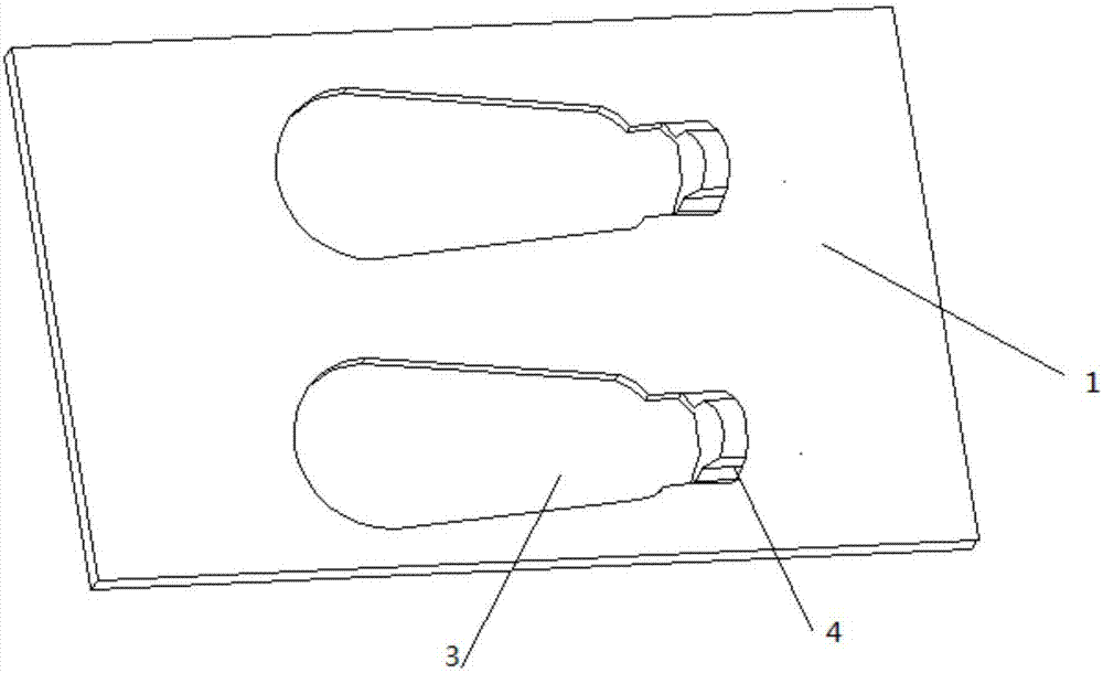
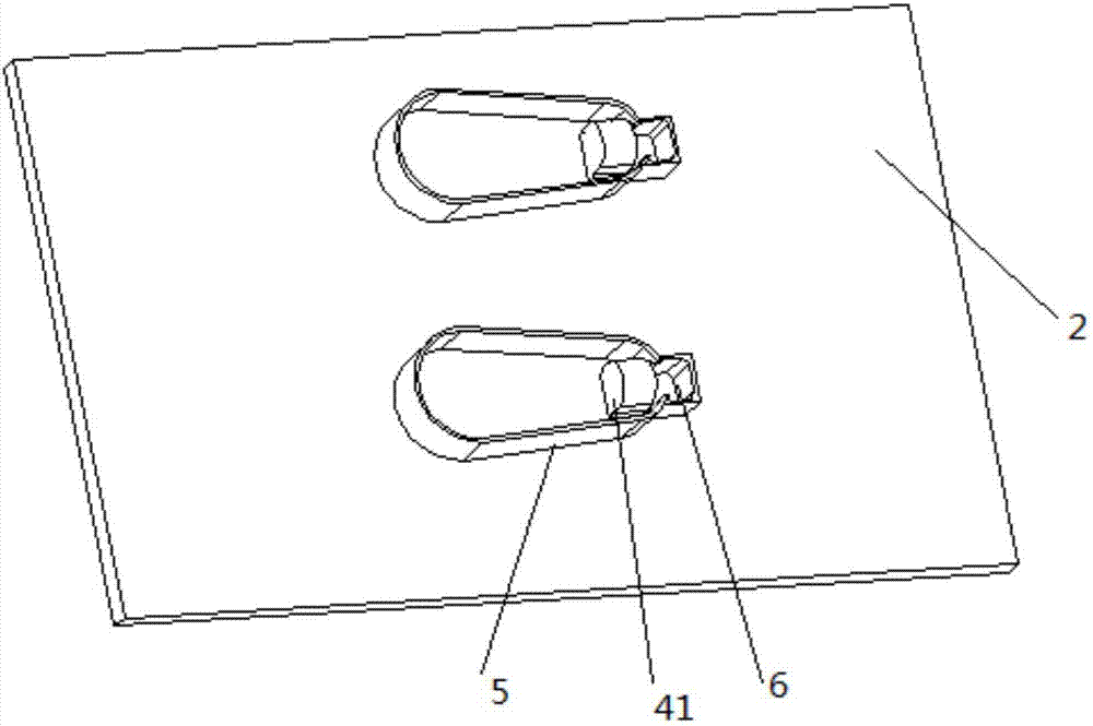
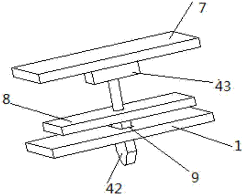
[0016] Such as Figure 1-Figure 4 As shown, a full-automatic blister machine side punching equipment includes an upper wallboard 1 and a lower wallboard 2, a knife groove 3 is provided on the upper wallboard 1, and a knife groove 3 is provided on the lower wallboard 2. The matching laser blade 5 also includes a top plate 7, a moving plate 8, a punch knife 4, a punch female mouth 6 matched with the punch knife 4, and the punch female mouth 6 and the knife groove 3 The sides are connected, and the top plate 7, the moving plate 8 and the lower wall plate 2 are arranged in an up-and-down structure.

[0017] Wherein, the punch knife 4 is composed of a fixed knife 41, a moving knife 42 and a cylinder 43, the fixed knife 42 is fixed in the knife groove 3 and is close to the punch female port 6, and the cylinder 43 is fixed on the On the bottom surface of th...


PUM


Abstract

The invention provides a full-automatic plastic suction machine side punching cutter body structure. Cutter grooves are arranged on an upper wallboard; laser blades which are matched with the corresponding cutter grooves are arranged on a lower wallboard; the full-automatic plastic suction machine side punching cutter body structure also comprises a top plate, a moving plate, punch cutters and punch mother holes which are matched with the corresponding punch cutters and are connected with side edges of the corresponding cutter grooves; each punch cutter is composed of a fixed cutter, a moving cutter and a cylinder; each fixed cutter is fixed in the corresponding cutter groove, close to the corresponding punch mother hole; each cylinder is fixed on the bottom surface of the top plate; the free end of a telescopic shaft of each cylinder is fixedly connected with the top surface of the moving plate; each moving cutter is fixed to the bottom surface of the moving plate; through grooves are arranged on the lower wallboard, close to the corresponding cutter grooves; and each cutter groove penetrates through each through groove. By adopting the full-automatic plastic suction machine side punching cutter body structure provided by the invention, shape cutting and side punching of a plastic product are finished full-automatically once, so that the traditional processing technology is changed, and the labor efficiency is improved; and by adopting the side punching shearing cutter structure, abrasion of the punch cutters is reduced, and the reject rate is lowered.

Description

technical field [0001] The present application relates to the field of plastic cutting equipment, in particular to a side punching cutter body structure of a fully automatic blister machine. Background technique [0002] The existing production process of side punching is to realize the hollowing out of the side position of the product by punching the punch through the cooperation of the sub-mother and the cutting. A slight deviation can cause damage to the cutting edge of the knife. At the same time, after the punch knife has been used for a period of time, due to the wear of the punch knife, the gap between the mother and the mother knife increases. After punching, burrs appear on the edge of the measuring hole. If it is light, it needs to increase manpower and use a hot air gun to bake it off. Contents of the invention [0003] The technical problem to be solved by the present invention is to provide a side punching knife body structure of a fully automatic plastic abs...

Claims


Application Information

Patent Timeline
Patent Type & Authority Applications(China)
IPC IPC(8): B26F1/02B26F1/14B26F1/38B26D7/26B29C51/26B23K26/38
CPCB23K26/38B26D7/2614B26D7/2628B26F1/02B26F1/14B26F1/38B29C51/266B29C51/268
Inventor 谢长生
Owner TIANJIN HENGFENGDA PACKAGING PROD
Why Eureka
Try Eureka