Automatic feeding mechanism for down lamp lug buckle

An automatic feeding and ear buckle technology, which is applied to vibrating conveyors, conveyors, conveyor objects, etc., can solve the problems of difficult automatic regular transportation of ear buckles, wrong arrangement of large and small ends, and 300 overlapping ear buckles. Simple, easy to install automatically, easy to install

Active Publication Date: 2017-11-24
FOSHAN ELECTRICAL & LIGHTING
View PDF7 Cites 7 Cited by
  • Summary
  • Abstract
  • Description
  • Claims
  • Application Information

AI Technical Summary

Problems solved by technology

[0003] During actual operation, the thicker end of the earbud 300 needs to face the rear end of the main housing 100, that is, the position of the earbud 300 needs to be fixed. At this time, if the earbud 300 is to be automatically installed on the On the side wall of the main housing 100, the ear buckles 300 need to be automatically arranged first, and in the process of automatically arranging the ear buckles 300, since the two ends of the ear buckles have different irregular structures, the ear buckles 300 will There are problems such as overlapping and wrong arrangement of large and small ends. It can be seen that it is extremely inconvenient to automatically install the earbuckle 300 on the main housing 100 of the downlight, and it is difficult to solve the problem of automatic regular delivery of the earbuckle. If there is technology, the alignment of the earbuds 300 is generally done manually

Method used


Image

  • Automatic feeding mechanism for down lamp lug buckle
  • Automatic feeding mechanism for down lamp lug buckle
  • Automatic feeding mechanism for down lamp lug buckle

Examples


Embodiment Construction

[0039] In order to make the object, technical solution and advantages of the present invention clearer, the present invention will be further described in detail below in conjunction with the accompanying drawings. It is only stated here that the words for directions such as up, down, left, right, front, back, inside, and outside that appear or will appear in the text of the present invention are only based on the accompanying drawings of the present invention, and are not specific to the present invention. limited.

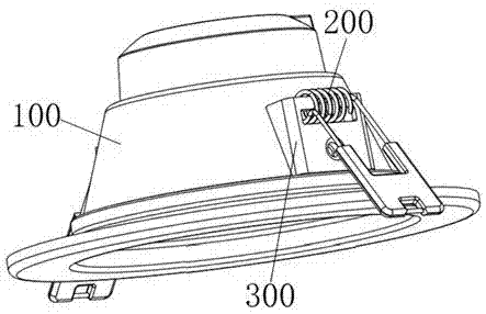
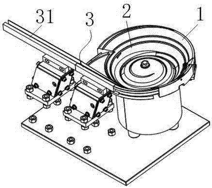
[0040] See attached image 3 To attach Figure 11 , the invention discloses an automatic feeding mechanism for downlight earbuds, including a vibrating plate 1 for placing the earbuds, a vibrating track 2 arranged around the side wall of the vibrating plate 1, and a flat feeding track 3 connected to the end of the vibrating track 2 .

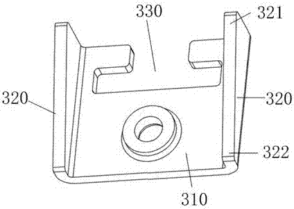
[0041] The bottom surface of the vibrating track 2 is an inclined surface 21 arranged obliquely downward from the inside to th...


PUM


Abstract

The invention discloses an automatic feeding mechanism for a down lamp lug buckle. The mechanism comprises a vibrating disc used for holding the lug buckle, a vibrating rail arranged around the side wall of the vibrating disc, and a horizontal feeding rail connected with the tail end of the vibrating rail. The bottom surface of the vibrating rail is an inclined surface which is arranged obliquely downwards from inside to outside. The lower end of the inclined surface is provided with a stopping edge used for preventing the lug buckle from falling off. The vibrating rail comprises an overlapping rejecting segment, an outwards turning rejecting segment, a reverse end rejecting segment, a rotating guide segment and an overturning guide segment which are arranged in sequence. Overlapping rejecting bars are mounted on the overlapping rejecting segment; at least part of the portion, located at the outwards turning rejecting segment, of the stopping edge is provided with short edge segments; the portion, located at the reverse end rejecting segment, of the inclined surface is provided with a rejecting port and an upwards pushing bar; the rotating guide segment is provided with a rotating guide mechanism used for driving the lug buckle to rotate and enabling the thin end of the lug buckle to face forwards ; and the overturning guide segment is provided with an overturning guide mechanism used for driving the lug buckle to overturn until a main plate portion faces upwards. By adopting the automatic feeding mechanism provided by the invention, the lug buckle can be automatically fed unidirectionally.

Description

technical field [0001] The invention relates to the technical field of downlight processing equipment, in particular to an automatic feeding mechanism for spring ear buckles of downlights. Background technique [0002] See attached figure 1 As shown, in order to facilitate the installation of the downlight, it is necessary to set spring clips 200 on both sides of the main housing 100 of the downlight. In the installation hole, release the spring clip 200 after reaching a certain position, and the spring clip 200 will automatically go down to hold the downlight, wherein the spring clip 200 is positioned by the ear buckles 300 on both sides of the main housing 100, The structure of the earbud 300 is detailed in the attached figure 2 As mentioned above, the ear buckle 300 includes a main board part 310 and slant board parts 320 arranged on both sides of the main board part 310. One end of the main board part 310 is provided with a locking notch 330 for locking the spring cli...

Claims


Application Information

Patent Timeline
Patent Type & Authority Applications(China)
IPC IPC(8): B65G27/02B65G47/256B65G47/248
CPCB65G27/02B65G47/248B65G47/256
Inventor 张勇杨金思杨青周李宁
Owner FOSHAN ELECTRICAL & LIGHTING
Why Eureka
Try Eureka