
A flexible feeder

A feeder and flexible technology, applied in the field of automated production, can solve the problem of feeding incompatible materials with differences, and achieve the effects of strong horsepower, accelerated feeding efficiency, and high transportation rate

Active Publication Date: 2020-06-26
POLYGON AUTOMATION TECH CHENGDU
View PDF5 Cites 0 Cited by
  • Summary
  • Abstract
  • Description
  • Claims
  • Application Information

AI Technical Summary

Problems solved by technology

[0005] The purpose of the present invention is to address the above-mentioned deficiencies in the prior art and provide a flexible feeder to solve the problem that the prior art is not compatible with the feeding of differentiated materials under the premise of small batches, multiple varieties and short life cycles.

Method used


Image

  • A flexible feeder
  • A flexible feeder
  • A flexible feeder

Examples


Embodiment Construction

[0035] The specific embodiments of the present invention are described below so that those skilled in the art can understand the present invention, but it should be clear that the present invention is not limited to the scope of the specific embodiments. For those of ordinary skill in the art, as long as various changes Within the spirit and scope of the present invention defined and determined by the appended claims, these changes are obvious, and all inventions and creations using the concept of the present invention are included in the protection list.

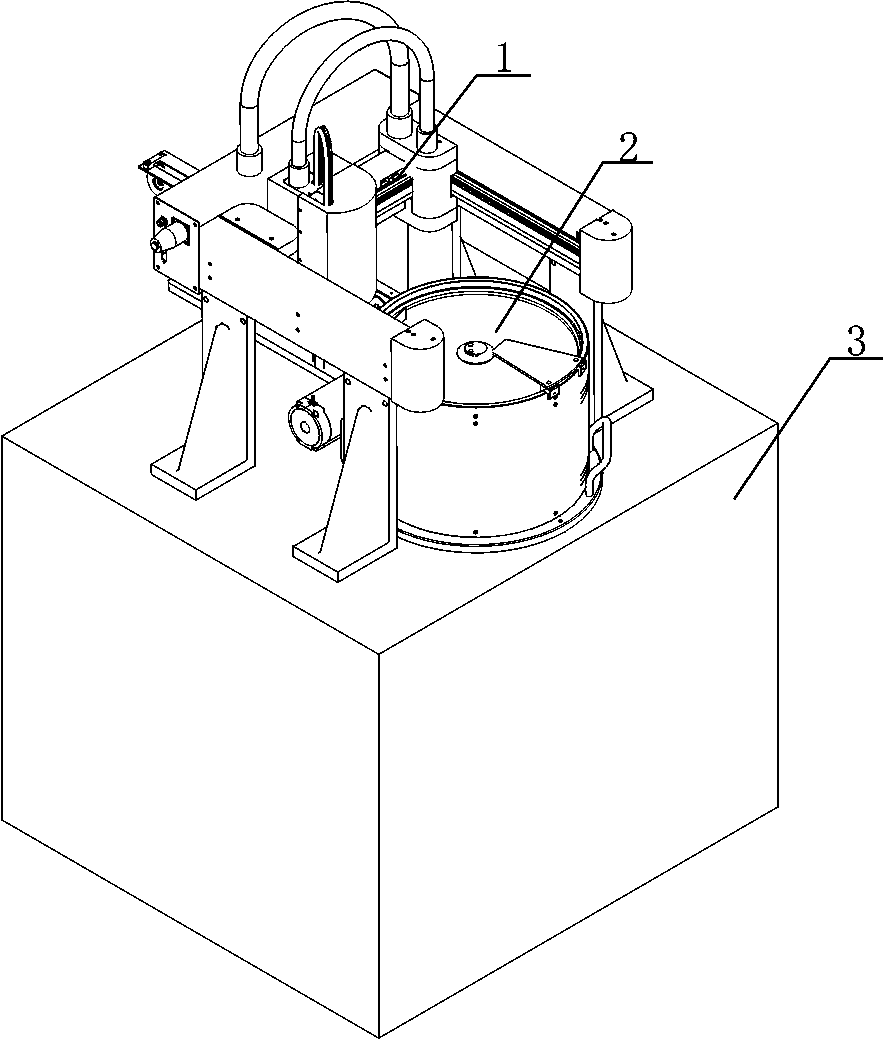
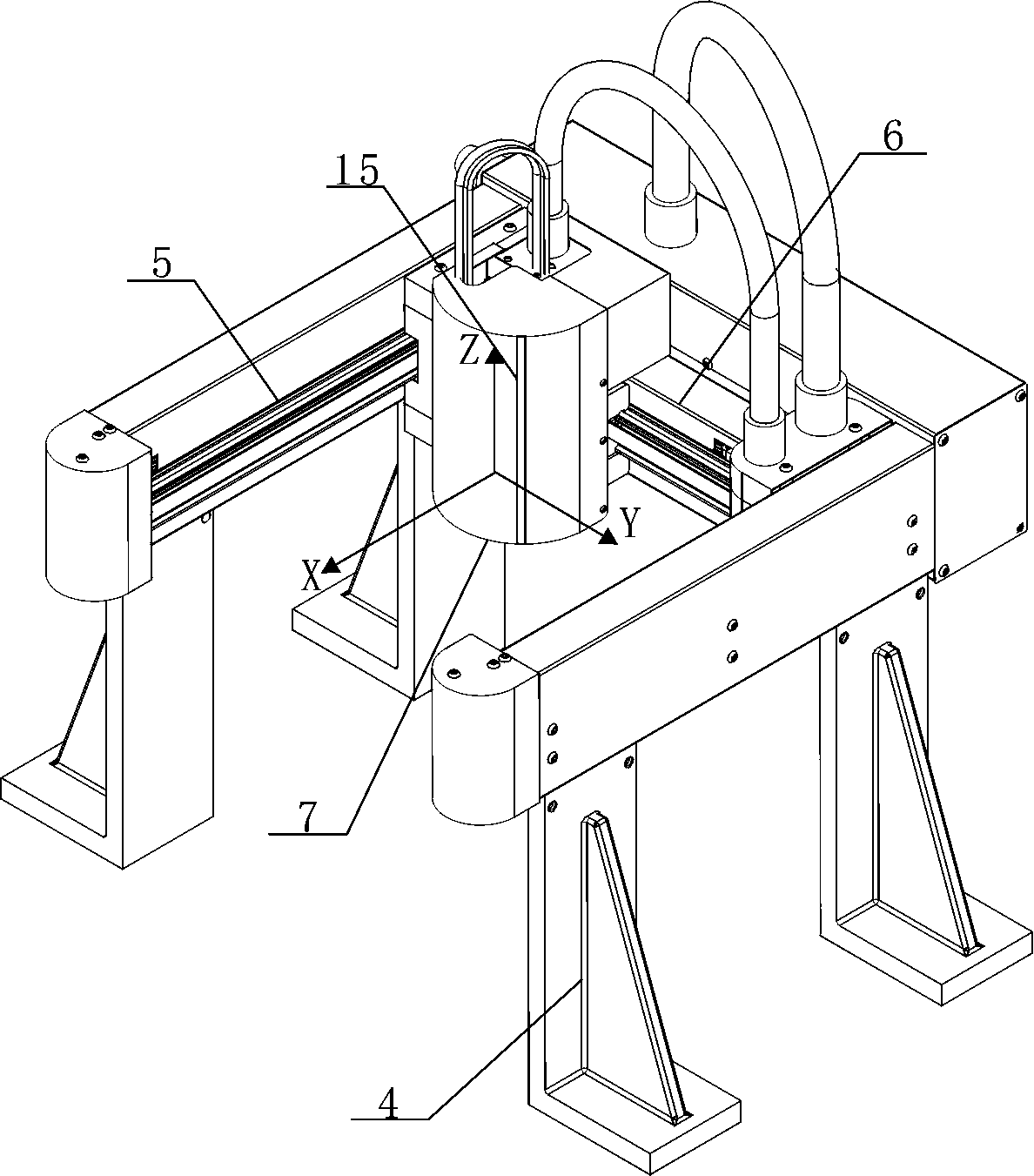
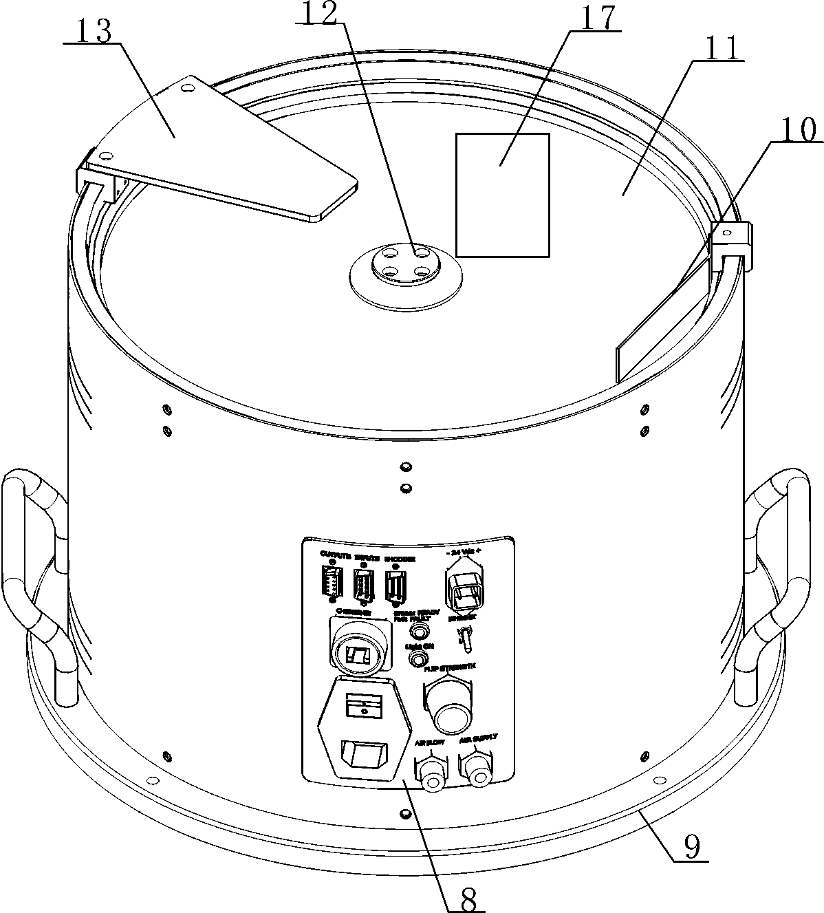
[0036] According to an embodiment of the present application, such as Figure 1-6 As shown, the flexible feeder of this solution includes a grabbing module 1, a storage bin 2 and a cabinet 3. The grabbing module 1 is fixed on the cabinet 3 , the storage bin 2 is installed in the space formed by the grabbing module 1 and the cabinet 3 , and the storage bin 2 and the grabbing module 1 are both accommodated in the protective c...


PUM


Abstract

The invention discloses a flexible feeder. The flexible feeder comprises a gripping module which is fixed to a machine cabinet. A storage bin is fixed in the space defined by the gripping module and the machine cabinet. The gripping module comprises a first conveying line in the X-axis direction, a second conveying line connected with the first conveying line in the Y-axis direction, and a gripping chuck in the Z-axis direction. A servo motor is arranged in the gripping chuck, and a gripper for gripping materials is fixed outside the gripping chuck. A selecting disc is arranged on the top of the storage bin. A rotary shaft linked with the selecting disc is arranged in the center of the selecting disc. A guide plate is arranged at the edge of the selecting disc. A selecting area is arranged in the position, close to the guide plate, of the selecting disc. An image collector is arranged in the position, over the selecting area, of the gripping module. A programmable logic controller (PLC) is contained in the machine cabinet and electrically connected with the servo motor, the gripper and the image collector.

Description

technical field [0001] The invention belongs to the technical field of automatic production, and in particular relates to a flexible feeder. Background technique [0002] At present, due to the increasing demand of consumers for customized products, in order to meet the needs of different consumers, manufacturers tend to develop in the direction of small batches, multiple varieties and short life cycles in the design and production of their own products. The automation solutions for large-scale manufacturing of varieties are obviously not suitable for the needs of the development of the times. [0003] In terms of cost: multi-variety products require manufacturers to invest more in skill training costs for personnel, and the production of small batch products will reduce the proficiency of employees, resulting in unstable quality and increased quality costs, coupled with the current rise in labor wages , which greatly increases the manufacturing cost of the manufacturer. ...

Claims


Application Information

Patent Timeline
Patent Type & Authority Patents(China)
IPC IPC(8): B65G47/91
CPCB65G47/917
Inventor 任超张东龚太平
Owner POLYGON AUTOMATION TECH CHENGDU
Learn More