
Friction fixing anchor rod

A fixed bolt technology, which is applied in the installation of bolts, mining equipment, earthwork drilling, etc., can solve the problems affecting the installation of waterproof boards, the leakage of grouting fluid, and the exposed end of bolts is too long, so as to achieve reliable working principle , the effect of simple structure

Pending Publication Date: 2017-11-24
CHENGDU MODERN WANTONG ANCHOR TECH
View PDF9 Cites 4 Cited by
  • Summary
  • Abstract
  • Description
  • Claims
  • Application Information

AI Technical Summary

Problems solved by technology

In the construction of anchor bolts in railway tunnels, the method of grouting first and then inserting rods is used below the side wall, which can basically ensure the fullness of grouting, but this method cannot be used for arch anchors. s Choice
However, due to the current construction practice, the exposed ends of some anchors are too long (affecting the installation of waterproof boards), the anchors in the arch are easy to slip, and the phenomenon of grouting fluid leakage is more prominent

Method used


Image

  • Friction fixing anchor rod
  • Friction fixing anchor rod
  • Friction fixing anchor rod

Examples


Embodiment 1

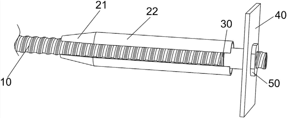
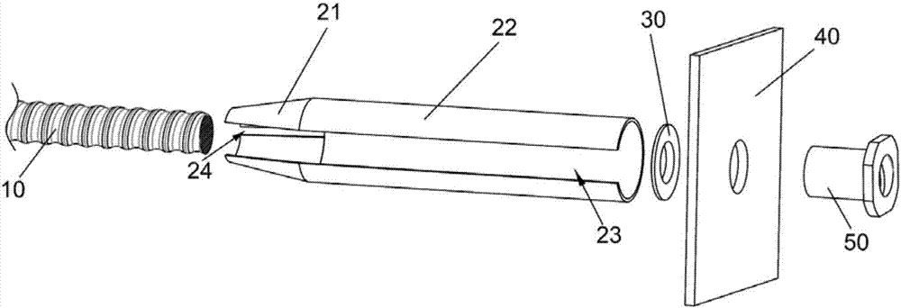
[0029] This embodiment provides a friction-fixed bolt, as attached figure 1 , attached figure 2 And attached Figure 5 As shown, countersunk nuts are selected in this embodiment, and the friction-fixed bolt includes a bolt body 10, and the outer surface of the bolt body 10 is set as a full thread, which is characterized in that it also includes a friction fixing sleeve and a sealing ring 30 , backing plate 40 and nut 50;

[0030] The friction fixing sleeve is set as a pipe body provided with a press-fit opening 23 along the length direction of the friction fixing sleeve. The friction fixing sleeve includes an integrally formed front tapered diameter reducing section 21 and a rear end straight pipe section 22. The tapered diameter reducing section A fastening port 24 is provided, and the anchor rod body 10 is arranged in the friction fixing sleeve. When the friction fixing sleeve is pushed into the anchor hole, the opening pipe body is compressed from large to small, and a l...

Embodiment 2

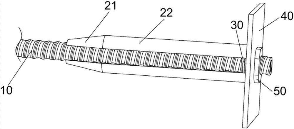
[0041] This embodiment provides a friction-fixed bolt, as attached image 3 , attached Figure 4 And attached Figure 5 As shown, in this embodiment, a hexagonal nut is selected. The friction-fixed bolt includes a bolt body 10, and the outer surface of the bolt body 10 is set to be fully threaded. It is characterized in that it also includes a friction fixing sleeve, a sealing ring 30, Backing plate 40 and nut 50;

[0042] The friction fixing sleeve is set as a pipe body provided with a press-fit port 23 along the length direction of the friction fixing sleeve. The friction fixing sleeve includes an integrally formed front tapered diameter reducing section 21 and a rear end straight pipe section 22. The tapered diameter reducing section A fastening port 24 is provided, and the anchor rod body 10 is arranged in the friction fixing sleeve. When the friction fixing sleeve is pushed into the anchor hole, the opening pipe body is compressed from large to small, and a large fricti...


PUM


Abstract

The invention discloses a friction fixing anchor rod which comprises an anchor rod body. The outer surface of the anchor rod body is full of thread, the anchor rod body further comprises a friction fixing sleeve, a size sealing ring, a subplate and a nut, the friction fixing sleeve is arranged to be a pipe with an opening along the length direction and comprises a front-end conical diameter contracting section and a rear-end straight pipe section which are formed integrally, the conical diameter contracting section is provided with a fastening port, and the anchor rod body is arranged in the friction fixing sleeve; the ring is arranged between the anchor rod body and the friction fixing sleeve, and the subplate is arranged on the outer surface of the anchor rod body in a sleeved manner, fixedly connected with the anchor rod body through the nut and arranged between the nut and the end of the rear-end straight pipe section. The friction fixing hollow anchor rod is mature and reliable in structure, simple to operate, high in sealability and suitable for injection of various sizes.

Description

technical field [0001] The invention belongs to the technical field of anchor rods, and in particular relates to a friction-fixed anchor rod. Background technique [0002] With the advancement of science and technology and the development of society, the use of anchor rods is widely used as an important support method in tunnel construction projects. The supporting functions of the anchor mainly include: anchor suspension, extrusion reinforcement, composite beam (arch) effect, etc., and its mechanism of action: Suspension: the anchor passes through the weak and loose rock formation, and is anchored in the deep On the rock formation, the unstable rock formation is suspended on the relatively stable natural balance arch above it; extrusion reinforcement: the bolt installed in the surrounding rock can form a compression zone within a certain range around it after it is stressed In the system bolt, multiple compression zones overlap each other to form a continuous compression z...

Claims


Application Information

Patent Timeline
IPC IPC(8): E21D21/00
CPCE21D21/0026E21D21/008
Inventor 吴航蒋亚张翩谢志萍王英芳
Owner CHENGDU MODERN WANTONG ANCHOR TECH
Learn More