Method and die for forming ceramics
A technology of ceramic products and molds, which is applied in the field of formed ceramic products, can solve the problems of simple shapes and unrealistic images of ceramic products, and achieve realistic image effects
- Summary
- Abstract
- Description
- Claims
- Application Information
AI Technical Summary
Problems solved by technology
Method used
Image
Examples
Embodiment 1
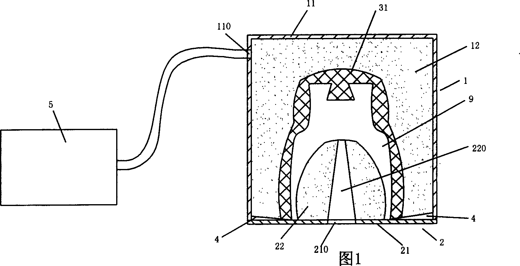
[0022] Embodiment one, as shown in Fig. 1, a kind of mold that is used for ceramic product forming of the present invention, comprises moving 1, fixed 2 molds and flexible cavity 31; Flexible cavity 31 is arranged on upper outer mold 12 inner cavity, and with The fixed fitting, the positioning and fitting of the movable and fixed molds, the outer casing is sealed, which is convenient for vacuuming, and a cavity 9 for forming ceramic products is formed inside; the movable mold 1 includes a movable mold shell 11 and an upper outer mold 12. The movable mold housing 11 is provided with an air extraction port 110 connected to the vacuum processing device 5, and the upper outer mold 12 is arranged in the movable mold housing 11; the fixed mold 2 includes a fixed mold housing 21 and a charging port 220 The lower outer mold 22, the lower outer mold 220 is arranged in the fixed mold housing 21, the fixed mold housing 21 is provided with a through hole 210 communicated with the charging ...
Embodiment 2
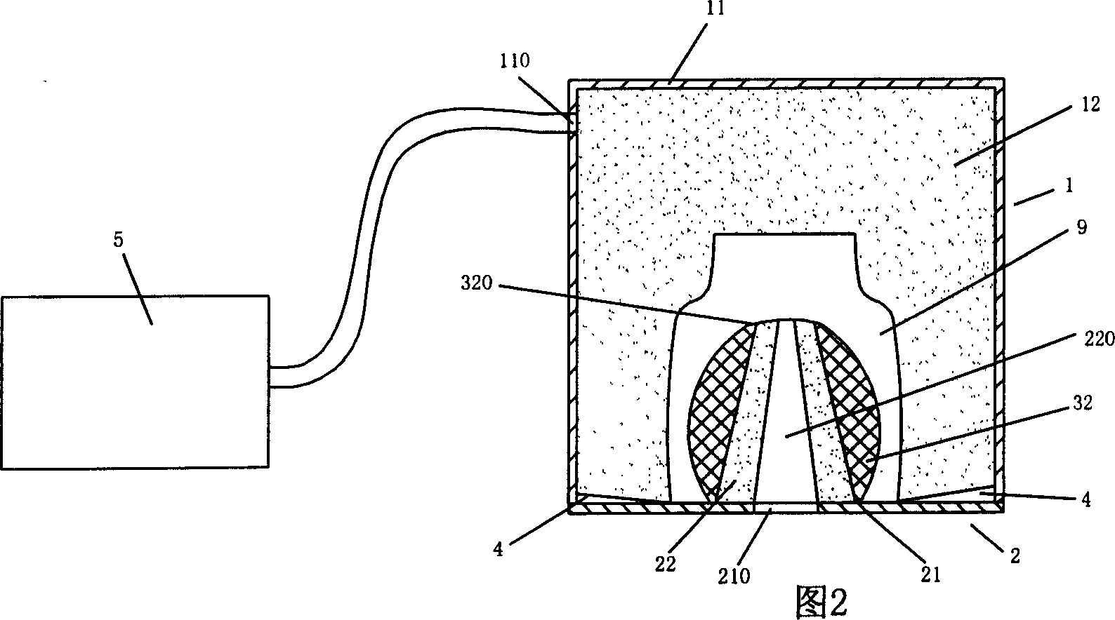
[0024] Embodiment 2, as shown in Fig. 2, a kind of mold that is used for ceramic product forming of the present invention, comprises moving 1, fixed 2 molds and flexible cavity 32, and moving, fixed mold positioning fits, and its outer casing is sealed, is convenient to Vacuumize, and a cavity 9 for forming ceramic products is formed inside; the movable mold 1 includes a movable mold housing 11 and an upper and outer mold 12 made of porous material, and the movable mold housing 11 is provided with a vacuum treatment device 5 is connected to the suction port 110, and the upper outer mold 12 is arranged in the movable mold housing 11; the fixed mold 2 includes a fixed mold housing 21 and a lower outer mold 22 made of porous material, and the lower outer mold 22 is arranged in the fixed mold housing 11. In the casing 11, the fixed mold casing 21 is provided with a through hole 210 communicating with the filling port 220 of the lower outer mold 22, and an exhaust channel 4 is provi...
Embodiment 3
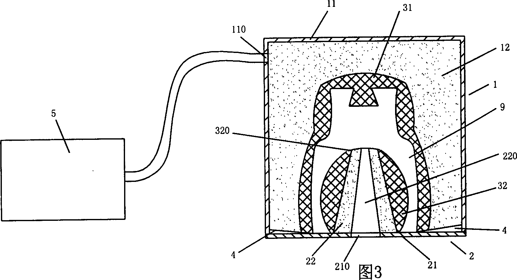
[0026] Embodiment 3, as shown in Fig. 3, another kind of mold used for ceramic product forming of the present invention, comprises moving 1, fixed 2 molds and flexible cavity 31, 32, and moving 1, fixed mold 2 are positioned and bonded, and its The outer casing is sealed for easy vacuuming, and a cavity 9 for forming ceramic products is formed inside; the movable mold 1 includes a movable mold casing 11 and an upper outer mold 12 made of a porous material, and the movable mold casing 11 is designed There is an air extraction port 110 connected to the vacuum processing device 5, and the upper outer mold 12 is arranged in the movable mold shell 11; the fixed mold 2 includes a fixed mold shell 21 and a porous material made of a porous material with a filling port 220 Lower outer mold 22, the lower outer mold 22 is arranged in the fixed mold housing 21, the fixed mold housing 21 is provided with the through hole 210 that is communicated with the charging port 220 of the lower outer...
PUM
 Abstract
Description
Claims
Application Information
 - R&D
- Intellectual Property
- Life Sciences
- Materials
- Tech Scout
- Unparalleled Data Quality
- Higher Quality Content
- 60% Fewer Hallucinations
Browse by: Latest US Patents, China's latest patents, Technical Efficacy Thesaurus, Application Domain, Technology Topic, Popular Technical Reports.
© 2025 PatSnap. All rights reserved.Legal|Privacy policy|Modern Slavery Act Transparency Statement|Sitemap|About US| Contact US: help@patsnap.com


