Heating type water storage structure for humidifier and humidifier comprising same

A humidifier and heating technology, used in heating methods, air humidification systems, lighting and heating equipment, etc., can solve the problems of large influence of heating elements, dry heating of the heating plate, and increase the cost of the whole machine, so as to avoid dry heating. Effect

Pending Publication Date: 2017-11-24
GREE ELECTRIC APPLIANCES INC
View PDF8 Cites 0 Cited by
  • Summary
  • Abstract
  • Description
  • Claims
  • Application Information

AI Technical Summary

Problems solved by technology

[0002] The main problem of hot mist humidifier failure is generally dry burning or water overflow, etc. Dry burning is caused by insufficient water in the heating area, which has a great impact on the heating element
However, the general circuitous waterway lacks the function of preventing the heating plate from drying out. The water flow first flows to the float switch water storage tank, and then flows to the heating plate water storage tank. In this way, when the water flow first flows to the float switch water storage tank, the float switch is sensed. When the power is turned on, the heating plate runs and generates heat. At this time, the water flow has not yet flowed into the water storage tank of the heating plate, and there is no water in the water storage tank of the heating plate, resulting in dry burning of the heating plate, which affects the service life of the heating plate.
[0004] The common method for avoiding dry burning in existing humidifiers is to install electronic components to detect and control the water level and the working status of heating elements, but this increases the cost of the whole machine and is not conducive to market promotion.

Method used


Image

  • Heating type water storage structure for humidifier and humidifier comprising same
  • Heating type water storage structure for humidifier and humidifier comprising same
  • Heating type water storage structure for humidifier and humidifier comprising same

Examples


Embodiment Construction

[0030] The present invention is described below based on examples, but the present invention is not limited to these examples. Those of ordinary skill in the art should understand that the drawings provided herein are for illustrative purposes, and the drawings are not necessarily drawn to scale.

[0031] Unless the context clearly requires, the words "including", "including" and other similar words in the entire specification and claims should be interpreted as inclusive rather than exclusive or exhaustive meanings; in other words, "including but not limited to" Meaning.

[0032] In the description of the present invention, it should be understood that the terms "first", "second", etc. are only used for descriptive purposes and cannot be understood as indicating or implying relative importance. In addition, in the description of the present invention, unless otherwise specified, "plurality" means two or more.

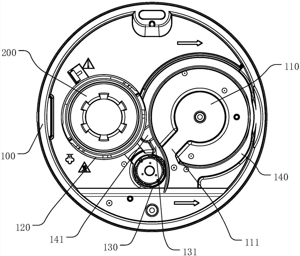
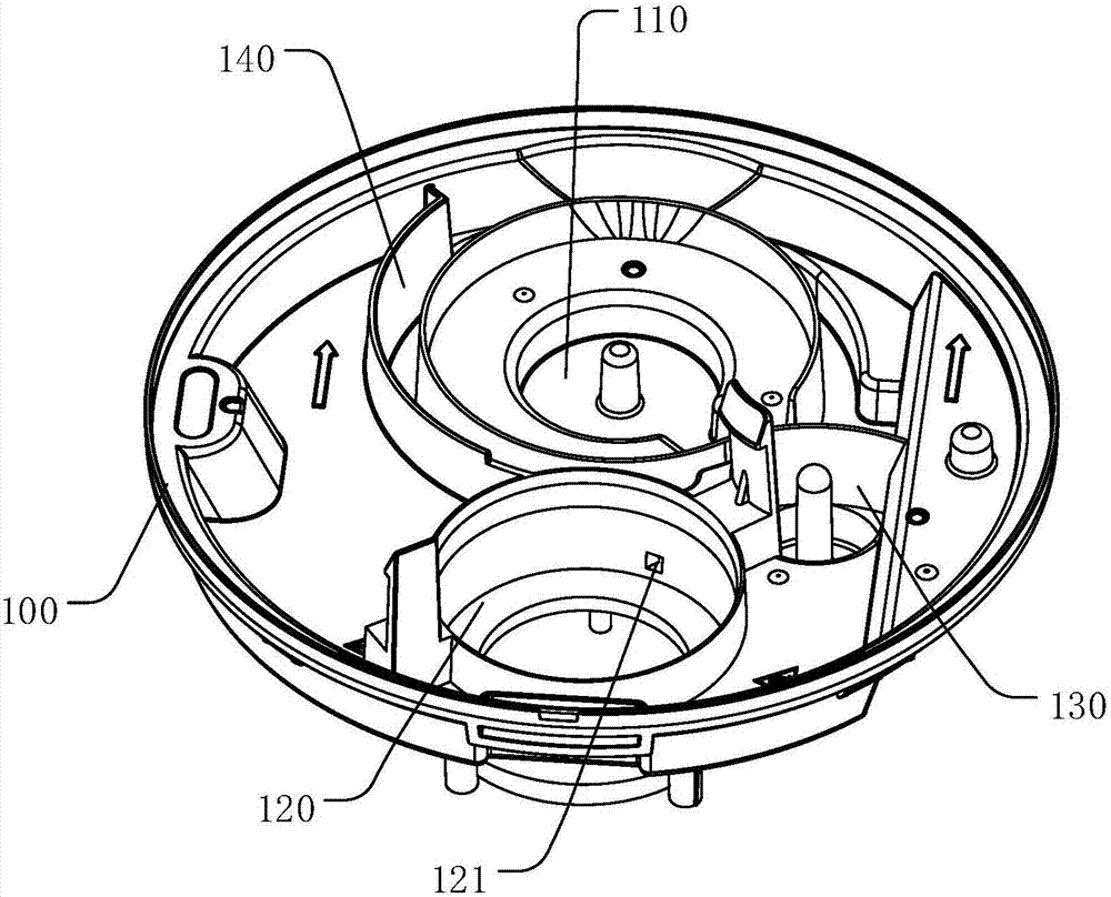
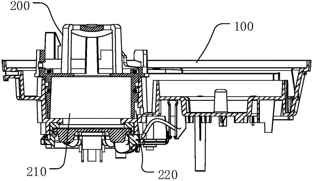
[0033] The water storage structure of the heating type humidifier prov...


PUM

PropertyMeasurementUnit
Sizeaaaaaaaaaa

Abstract

The invention discloses a heating type water storage structure for a humidifier and the humidifier comprising the heating type water storage structure. The heating type water storage structure comprises a cold water tank, a water heating tank and a liquid level switch water tank, wherein the cold water tank, the water heating tank and the liquid level switch water tank communicate with one another through a water supply channel, after flowing out from the cold water tank, water flows into the water heating tank and the liquid level switch water tank along the water supply channel, and the water firstly flows into the water heating tank before flowing into the liquid level switch water tank. According to the heating type water storage structure, the cold water tank, the water heating tank and the liquid level switch water tank communicate with one another through the water supply channel, the water firstly flows into the water heating tank before flowing into the liquid level switch water tank, and therefore when the water in the liquid level switch water tank triggers a switch, a certain amount of water already exists in the water heating tank, and the condition that heating elements are dry-burned is avoided.

Description

Technical field [0001] The invention relates to the related technical field of humidifiers, in particular to a water storage structure of a heating type humidifier and a humidifier having the same. Background technique [0002] The main problems of hot mist humidifier failure are generally dry burning or overflowing. Dry burning is caused by insufficient water in the heating area, which has a greater impact on the heating element. Overflow is generally caused by the return of water from the hot water tank to the cold water tank, causing the water temperature of the cold water tank to be too high. [0003] Existing humidifiers usually use a circuitous water path between the cold water tank and the hot water tank to extend the communication path to prevent a large amount of hot water in the hot water tank from returning, or to cool the hot water during the return process to prevent cold water The water temperature in the tank is too high. However, the general circuitous waterway la...

Claims


Application Information

Patent Timeline
IPC IPC(8): F24F6/10F24F11/02F24F13/00
CPCF24F6/10F24F13/00F24F2006/008Y02B30/70
Inventor 林志荣王威侯剑飞林振华
Owner GREE ELECTRIC APPLIANCES INC
Why Eureka
Try Eureka