
Temperature measuring device, temperature measuring system and control method of cooking appliance

A technology of cooking utensils and temperature measuring devices, which is applied in the field of temperature measuring devices, can solve problems such as hysteresis, inaccurate temperature values ​​of pots, and inability to turn off cooking utensils in time, and achieve the effect of preventing dry burning

Pending Publication Date: 2018-11-02
FOSHAN SHUNDE MIDEA ELECTRICAL HEATING APPLIANCES MFG CO LTD
View PDF6 Cites 5 Cited by
  • Summary
  • Abstract
  • Description
  • Claims
  • Application Information

AI Technical Summary

Problems solved by technology

[0002] Currently common cooking utensils on the market, such as induction cooker, the pot temperature sensor is usually installed on the lower surface of the microcrystalline panel of the induction cooker, that is, there is a layer between the pot temperature sensor and the pot, which makes the pot temperature sensor The temperature sensor does not directly detect the temperature of the pot. The temperature value of the pot detected by this indirect temperature measurement method is not only very inaccurate, but also has obvious hysteresis, which makes it impossible to turn off the cooking utensils in time when the pot is dry. , to protect the pot

Method used


Image

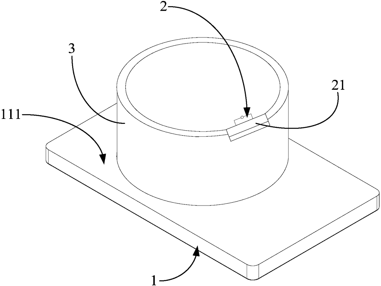
  • Temperature measuring device, temperature measuring system and control method of cooking appliance
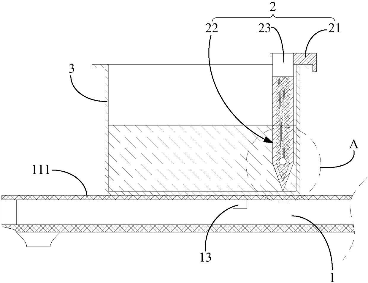
  • Temperature measuring device, temperature measuring system and control method of cooking appliance
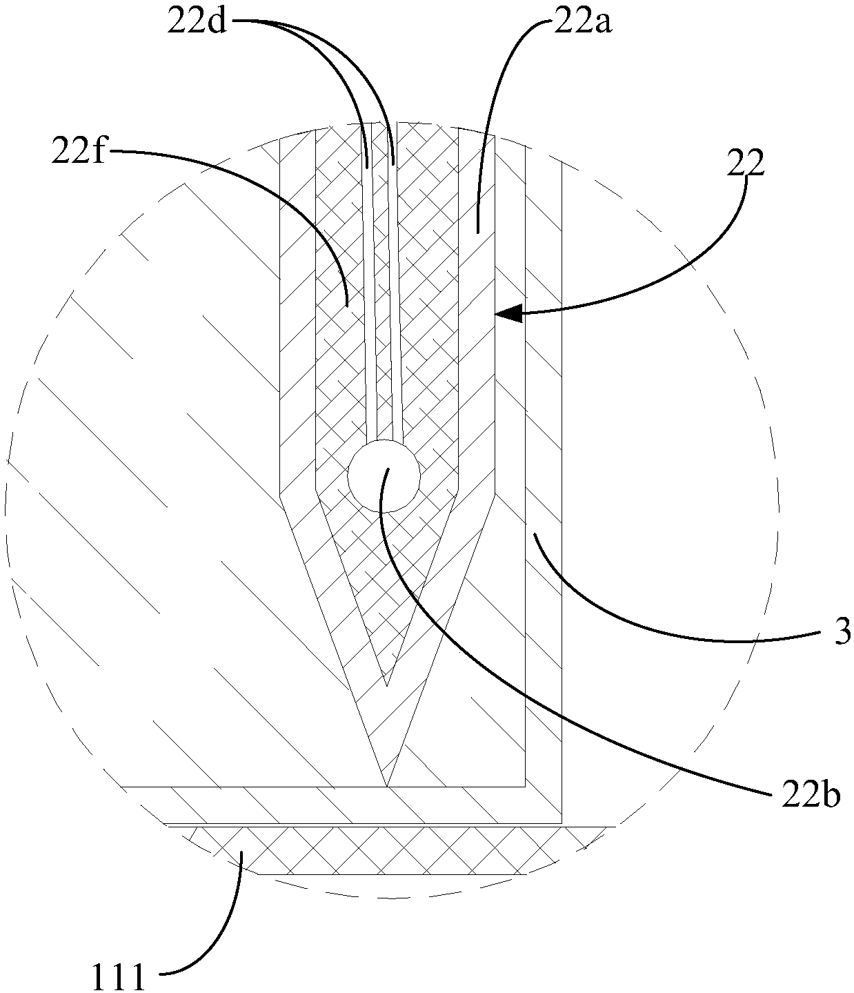
  • Temperature measuring device, temperature measuring system and control method of cooking appliance

Examples


Embodiment Construction

[0034] The following will clearly and completely describe the technical solutions in the embodiments of the present invention with reference to the accompanying drawings in the embodiments of the present invention. Obviously, the described embodiments are only part of the embodiments of the present invention, not all of them. Based on the embodiments of the present invention, all other embodiments obtained by persons of ordinary skill in the art without creative efforts fall within the protection scope of the present invention.

[0035] It should be noted that if there is a directional indication (such as up, down, left, right, front, back...) in the embodiment of the present invention, the directional indication is only used to explain the position in a certain posture (as shown in the accompanying drawing). If the specific posture changes, the directional indication will also change accordingly.

[0036] In addition, if there are descriptions involving "first", "second" and ...


PUM


Abstract

The invention discloses a temperature measuring device, a temperature measuring system and a control method of a cooking appliance. The temperature measuring device is used for a cooking appliance, and comprises a mounting part, a first temperature measuring module and a first communication module; the mounting part is used for detachably mounting on the side wall of the pot arranged on the cooking appliance; the first temperature measuring module is fixedly connected with the mounting part, and is used for detecting the near-bottom temperature of a preset height position of the bottom wall ofthe pot body; the first communication module is electrically connected with the first temperature measuring module and is used for sending the near-bottom temperature to the cooking appliance. The invention also discloses a control method of a cooking appliance. When the near-bottom temperature meets the preset condition, the control module of the cooking appliance controls the heating device tostop heating. The technical scheme can improve the accuracy of the detection of the temperature of the cooking appliance, and prevent the dry burning.

Description

technical field [0001] The invention relates to the field of cooking utensils, in particular to a temperature measuring device, a temperature measuring system and a control method for the cooking utensils. Background technique [0002] Currently common cooking utensils on the market, such as induction cooker, the pot temperature sensor is usually installed on the lower surface of the microcrystalline panel of the induction cooker, that is, there is a layer between the pot temperature sensor and the pot, which makes the pot temperature sensor The temperature sensor does not directly detect the temperature of the pot. The temperature value of the pot detected by this indirect temperature measurement method is not only very inaccurate, but also has obvious hysteresis, which makes it impossible to turn off the cooking utensils in time when the pot is dry. , to protect the pot. Contents of the invention [0003] The main purpose of the present invention is to provide a tempera...

Claims


Application Information

Patent Timeline
Patent Type & Authority Applications(China)
IPC IPC(8): A47J36/24G01K1/02G01K1/14G01K7/22G08C17/02G05D23/32
CPCA47J36/2483G05D23/32G08C17/02G01K1/02G01K1/14G01K7/22A47J2201/00
Inventor 刘志才王志锋马志海区达理冯江平王帅刘经生梅长云伍世润尹二强范志荣李小龙
Owner FOSHAN SHUNDE MIDEA ELECTRICAL HEATING APPLIANCES MFG CO LTD
Learn More