
Cooling device of material pushing mechanism

A technology of cooling device and pushing mechanism, which is applied in the field of machinery, can solve problems such as reducing service life, and achieve the effects of accelerating heat loss, accelerating diffusion, and improving service life

Active Publication Date: 2017-11-24
江苏希沐新材料有限公司
View PDF6 Cites 0 Cited by
  • Summary
  • Abstract
  • Description
  • Claims
  • Application Information

AI Technical Summary

Problems solved by technology

Due to the uniform cooling and good effect of the water-cooling system, the water-cooling system is widely used in the current equipment. In some pushing mechanisms, the material plate moves back and forth on the shaft to achieve the effect of pushing the material, but the relative movement of the material plate and the shaft , the friction between the two will generate a lot of heat, which greatly reduces the service life of the shaft, so we propose a cooling device for the pushing mechanism

Method used


Image

  • Cooling device of material pushing mechanism
  • Cooling device of material pushing mechanism

Examples


Embodiment Construction

[0012] The technical solutions in the embodiments of the present invention will be clearly and completely described below in conjunction with the accompanying drawings in the embodiments of the present invention. Obviously, the described embodiments are only a part of the embodiments of the present invention, rather than all the embodiments. Based on the embodiments of the present invention, all other embodiments obtained by those of ordinary skill in the art without creative work shall fall within the protection scope of the present invention.

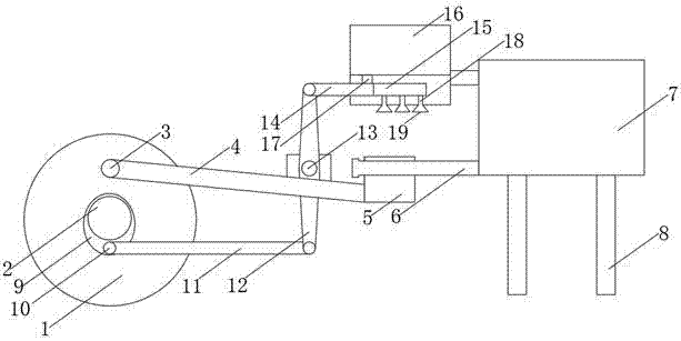
[0013] See Figure 1-2 , The present invention provides a technical solution: a cooling device for a pushing mechanism, comprising an active turntable 1, which is a transmission device, and an active rotating shaft 2 is fixedly inserted in the middle of the active rotating disk 1, and the active rotating shaft 2 passes through a motor Driven to provide power for the rotation of the active turntable 1. The upper front end of the active tu...


PUM


Abstract

The invention discloses a cooling device of a material pushing mechanism. The cooling device comprises a driving rotary disk. A driving rotary shaft is connected to the middle of the driving rotary disk in an inserted mode. The upper portion of the front end of the driving rotary disk is connected with a push rod through a first connecting shaft. The right end of the push rod is fixedly connected with the lower portion of the left end of a push plate. The upper portion of the push plate is connected to a sliding shaft in an inserted mode. The right end of the sliding shaft is fixedly connected to a fixing platform. The four corners of the lower end of the fixing platform are fixedly provided with supporting legs. The middle portion of the front end of the driving rotary disk is fixedly provided with an elliptic rotary disk. The lower portion of the elliptic rotary disk is connected with a first connecting rod through a second rotary shaft. The right end of the first connecting rod is connected to the lower end of a fixed rod through a pin. The cooling device of the material pushing mechanism guarantees the stability of the surface temperature of the sliding shaft through the overall structure of equipment and effectively accelerates heat loss of the sliding shaft through a capillary groove structure.

Description

Technical field [0001] The invention relates to the technical field of machinery, in particular to a cooling device of a pushing mechanism. Background technique [0002] The main function of the cooling system is to dissipate part of the heat absorbed by the heated parts in time to ensure that the equipment works at the most suitable temperature. The cooling system can be divided into air-cooled and water-cooled according to different cooling media. If the heat of the high-temperature parts in the equipment is directly dissipated into the atmosphere to cool the device, it is called an air-cooled system, and the heat is first transferred to the cooling water and then dissipated. The device that enters the atmosphere for cooling is called a water cooling system. Due to the uniform cooling of the water cooling system, the effect is good. At present, the water cooling system is widely used in the equipment. In some pushing mechanisms, the material plate is moved back and forth on th...

Claims


Application Information

Patent Timeline
Patent Type & Authority Applications(China)
IPC IPC(8): F25D1/02
CPCF25D1/02
Inventor 马玲桑青桐
Owner 江苏希沐新材料有限公司
Features
  • Generate Ideas
  • Intellectual Property
  • Life Sciences
  • Materials
  • Tech Scout
  • Unparalleled Data Quality
  • Higher Quality Content
  • 60% Fewer Hallucinations
Learn More